The overwhelming majority of locks that are in use today, particularly in North America, are either pin tumbler locks or wafer locks. A handful of other designs are prevalent in certain international regions. Lever locks, for example, are an older design originating in the 17th century with keys that tend to be larger and their operation more cumbersome than more recent designs. These are a common sight in Europe, central Asia, and parts of South America. Rotating disk mechanisms are popular in northern Europe and parts of the Pacific Rim, while some locks in Austria and Japan feature magnetic components. However, in all cases—even in the regions outside of North America—it should be understood that these designs are usually not nearly as prominent as basic pin tumbler locks and wafer locks, particularly as far as penetration testing is concerned.
Typical office doors, desk drawers, filing cabinets, and access panels will usually be equipped by default with lower quality locks because they are the easiest to mass produce, the simplest to service, and the most economical to replace or re-key should the need arise. Until furniture manufacturers and hardware stores cease ordering bulk shipments of locks with low production costs and lax quality standards, we are likely to continue encountering them for a very long time.
Pin Tumbler Locks
The style of lock with which the majority of people are most familiar is the pin tumbler design. I realize that many of you may already be somewhat aware of this hardware (and, indeed, diagrams and photographs of all shapes and sizes seem to abound on the internet and in other printed works), but I feel it would be helpful for us to analyze this mechanism briefly, from the ground up, in order to properly understand how it functions and how it can be exploited.
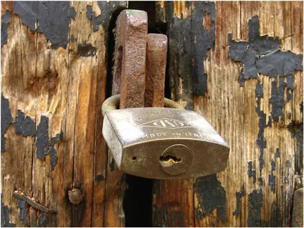
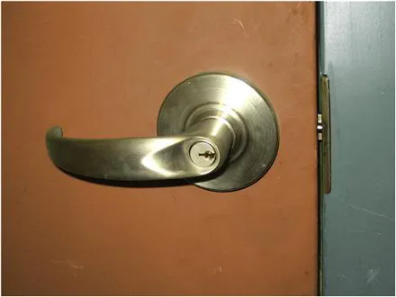
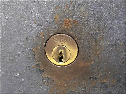
Pin tumbler locks come in many forms and styles and can be incorporated into hardware that appears in a number of different shapes. Take a look at the locks in Figures 1.1, 1.2, and 1.3.
Figure 1.1 A padlock featuring an embedded pin tumbler mechanism.
Figure 1.2 A doorknob featuring a key-in-knob pin tumbler core.
Figure 1.3 A deadbolt featuring a pin tumbler lock in a mortise cylinder.
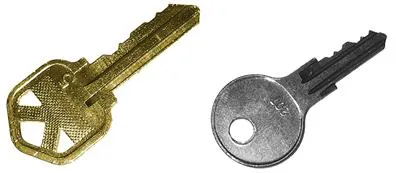
While each lock is clearly a very different form factor, all three function with a traditional pin tumbler mechanism which is operated by means of a simple “blade” style key, shown in Figure 1.4, the likes of which you have seen multiple times before.
Figure 1.4 Blade style keys, which feature bitting cuts along their thin edge. Many well-known manufacturers’ keys can be identified simply by the shape of the key’s bow.
The pin tumbler mechanism is one of the oldest lock designs in existence and is still widely used today. Let’s take a closer look at how the components of these locks are made and assembled, paying particular attention to how the lock attempts to hold itself shut without the key present. There are two primary large pieces that comprise the bulk of a pin tumbler lock: the housing and the plug. These are the two items that can easily be seen from an exterior perspective and are thus the most understood. We will now walk through the manner in which these two segments are fabricated and how they fit together.
The plug
The plug of a pin tumbler lock is constructed from a cylindrical billet, typically made of brass although occasionally steel is used in high quality models. Often the first feature to be added, after the metal is cut to the requisite length, is a small divot in what will become the front face of the plug. This helps to seat and align the key during user operation. See Figure 1.5 for a better understanding of how we shall look upon the various components of lock hardware. On the left is a frontal view, what the user would typically see from a straightforward perspective. On the right of the diagrams in Figures 1.5 through 1.12 we see a perspective from the side.
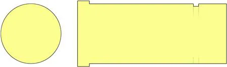
Figure 1.5 A blank plug featuring the key-seating divot, ready for milling.
Figure 1.6 The left side of the diagrams in Figures 1.6 through 1.12 will begin to focus on a cross-section slightly inward from the exterior front facing surface of the lock.
Figure 1.7 The milled lip at the front of a plug. Note how our “front perspective” on the left side has reduced in size slightly, since we are focusing our attention on a cross-section approximately 5 mm inward from the front face.
Figure 1.8 The milled notch in the rear of the plug which will later accommodate a retaining clip. Some lock styles utilize a screw-on threaded end cap instead.
Figure 1.9 The keyway has now been milled into the plug. Note that it often extends fully through the bottom of the plug. This will come into play later when we discuss picking techniques and tool placement in Chapter 2.
Figure 1.10 Some additional milling has been cut into the rear of the plug in order to accommodate a tailpiece.
Figure 1.11 Five pin chambers have been milled into the plug. Our cross-section (on the left side of this diagram) is still focused on an area approximately 5 mm inward from the front face and thus is showing the first pin chamber as well as the keyway milling.
Figure 1.12 From the side perspective of our lock plug (on the right half of this diagram) we see the additional hole drilled in front of the pin chambers. It has been filled with both a steel ball bearing as well as a ceramic block.
Given that the bulk of what concerns us takes place further inside of the lock, we will begin to focus our “straight forward” view (on the left side of these diagrams) further inward. In Figures 1.6 through 1.12, that image will correlate to a cross-section of the plug (or the lock as a whole) approximately 5 mm in from the front face.
The plug will be milled with a small lip around the front facing edge. This is dual-purpose, in that it prevents the plug from sliding inward through the lock housing while also precluding a potential attacker’s insertion of material that could penetrate the front of the lock and interfere with the operation of the pin tumblers within.
It is quite common for this front milling process to be more intricate, involving additional ridges or deeper grooves. Again, this is to prevent pieces of thin metal or other tools from being inserted and worked into the depths of the lock from the outside.
In addition to th...