eBook - ePub
Analog Electronics
Circuits, Systems and Signal Processing
- 425 pages
- English
- ePUB (mobile friendly)
- Available on iOS & Android
eBook - ePub
About this book
The content has been carefully designed to meet the requirements of first and second year students of electronic engineering, communications engineering and telecommunications, following full honours degree programs or two-year courses including HNC/HND.
- A completely new analog electronics textbook for the digital age
- Coverage ideal for courses with a communications / wireless focus
Tools to learn more effectively

Saving Books

Keyword Search

Annotating Text

Listen to it instead
Information
1
Introduction to electronic systems
1.1 The roles of analog electronics and digital electronics
The purpose of this chapter is to clarify the distinction between analog and digital electronics, and to provide examples of systems in which both types of electronics are used, so as to set in context the analog circuit analysis and signal processing in the rest of the book. ‘Electronics’ is one of those words which most of us recognize, but which is quite hard to define. However, we usually mean apparatus and systems which use devices which amplify and process electrical signals, and which need a source of power in order to work. Most of the devices which do this are transistors. In the early days of electronics, the devices were vacuum-tubes (‘valves’) in which a stream of electrons was emitted from a heated cathode, via a control grid, towards an anode. This is probably where the name ‘electronics’ came from. (Beams of electrons in a vacuum are still used in the cathode-ray tubes used for displays in television receivers and computer monitors, and in microwave devices called magnetrons and travelling-wave tubes.)
The electrical signal from a microphone is an example of an analog signal; its waveform (graph of voltage against time) has a similar shape to the waveform of the sound waves which it ‘picks up’. The converse process, that of converting an electrical signal into a sound wave, also involves analog signals. The electrical analog signal is fed to a loudspeaker, which produces a sound waveform which is an analog of the original sound.
An example of a digital signal is that recorded on a compact disc (CD). If an analog signal from a microphone is to be recorded, then it must first be converted to digital form. This involves sampling the analog signal at a frequency much higher than the highest analog signal frequency, and then converting the sample amplitudes into corresponding digital codes represented by a series of electrical pulses. Further coding is used, first to ‘compress’ the total data and then to convert it into longer sequences for immunity against corruption. These sequences are stored on the disc as tiny ‘blips’ representing binary data.
All of the digital circuits use transistors, in sub-circuits called gates and flip-flops. So, both types of electronics have transistors in common. The design of the gate and flip-flop circuits, for ever-higher speed and lower power dissipation, depends heavily on the same circuit concepts as the analog circuits designed for higher frequencies and lower power dissipation. These are concepts such as the equivalent circuit of the transistor, stored charge, stray capacitance and inductance, input and output impedance, electrical noise and the like. Interconnections between sub-assemblies, whether for digital signals in the form of pulses, or for analog signals, must be designed with a knowledge of transmission line theory when high frequencies or high data rates (which incur high frequencies) are present. So, a great deal of the analog material of this book forms also the basic material of digital circuit design. The analog signal processing in the book is mirrored in digital signal processing, much of which is modelled on analog prototypes, and uses the same design theory, modified for digital implementation.
Thus, a good grounding in the theory of analog electronics is not only useful in its own right, but provides much of the background skills for the design of digital systems. The following examples illustrate the roles of analog and digital electronics in various systems.
1.2 Hi-fi and music amplifiers
We start with one of the most familiar uses of electronics, the amplification of speech and music. Figure 1.1 shows a blockdiagram of a typical set-up used by a group of musicians during a live performance. Each microphone converts sound waves into an electrical voltage, or electrical signal, which represents the sound. The electrical signals are conveyed by cables to an amplifier which boosts, or amplifies, the signals before passing them by cables, or radio, to the loudspeakers. The loudspeakers convert the electrical signals back into sound waves which, ideally, are the same as the original speech or music but at much higher intensities.
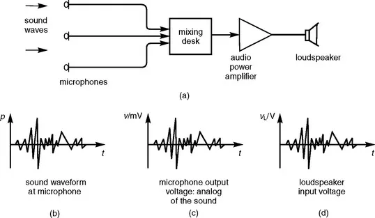
Fig. 1.1 Block diagram of a purely-analog sound amplification system.
In Figure 1.1, the form of the sound wave at a microphone is shown in a graph of the sound pressure (p) variation with time (t), called the waveform of the sound. The waveform of the electrical voltage (v) generated by the microphone has an almost identical shape. It is analogous to the sound waveform, so it is called an analog waveform, or analog signal. The microphone waveform has a typical peak voltage of some millivolts.
The typical peak voltages needed to provide enough sound from the loudspeakers in a concert hall are a few volts, or tens of volts. So it is quite obvious that the microphone signal voltages need to be amplified by a factor of about one thousand or more. The amplifier has to have a voltage gain of about one thousand or more.
Suppose the signal from the microphone has a peak voltage of 10 mV, and the required output voltage from the amplifier is 20 V. What voltage gain is needed?

The amplifier also has to be able to provide a relatively high power output. Loudspeakers have input impedances of one of a few standard values, such as 4Ω,8Ω, or 15Ω. So a speaker input voltage of a few volts, or tens of volts, causes an input power of several watts. Suppose the input was a sine wave of 20 V rms, and the speaker input impedance appeared purely resistive with a value of 8Ω. What would be the input power?

The system of Figure 1.1 uses analog voltages throughout. The analog voltage from each microphone is increased in voltage by the amplifier, but it is still an analog of the original sound, and it is this boosted analog signal which is fed to the loudspeakers. So, Figure 1.1 is a purely analog system.
In a typical hi-fi (high fidelity) system, some of the components use analog signals, and some use digital.
Long-playing (LP) records, spinning at 33⅓ rpm, and the 45rpm EP, were the final development of the earliest recording medium, Edison’s phonograph cylinder, followed by the 78 rpm disc. All these recorded the sound as a side-to-side displacement of a groove in the surface; a visible graph, or analog, of the sound waveform. Records are played back by a pick-up in which a ‘stylus’ (sometimes called a ‘needle’) rides in the groove. Its side-to-side displacement produces an analog output voltage from the pick-up. Inevitably, wear and dust in the groove, and surface scratches, lead to ‘surface noise’, a problem which is largely avoided in CDs.
Audio-tape cassettes were a much later development. As in the earlier reel-to-reel technique, the sound is recorded as a magnetic analog signal on magnetic tape. In recording, the electrical signal from the microphone is fed to a coil called the recording head. This generates a varying magnetic field which induces a pattern of permanent magnetism in the magnetic coating on the tape as it passes over the recording head. On playback, the tape passes over the same head, causing a varying magnetic field which induces a varying voltage in the coil. Again the output is an analog voltage, and again it can suffer from noise. The ‘tape noise’ is caused by the granularity of the magnetic coating.
The CD is digital. The CD player picks up the digital signal from the CD, decodes it, and converts it back to an analog signal representing the original recorded sound. The digital signal on the CD consists of a series of ‘pits’ etched into a layer of the disc just below the surface. These pits represent the noughts and ones of a binary code which, in turn, represents the analog signal from the microphone which picked up the original sound. (The analog-to-digital and the digital-to-analog conversion processes are described in Chapter 7.) The tiny pits representing the binary-coded signal can easily be obscured by surface dust, finger-prints and the like, which cause errors in the recovered digital signal. However, because of the coding process, a great many errors can be tolerated before the decoded digital signal is corrupted. The output from the CD player is an analog signal with a peak voltage of 1 V or so, and with a very-low noise content. It has a very-high signal-to-noise ratio.
The radio tuner is a conventional radio, but without a power output stage. The latest types receive digital broadcasts, in which the audio signals are coded digitally before transmission.
All these components have two audio channels, for stereophonic sound reproduction. They all feed into a power amplifier, via a selector switch.
1.3 Video cameras and displays
There are two main types of electronic camera, the electron-tube type and the CCD type. The electron-tube (cathode ray) type has been used in various forms since the early days of television, and is still used for high-quality work. The later-developed CCD type is lighter and cheaper, and is used in ‘camcorders’, electronic news gathering (ENG), ‘webcams’ for Internet use, surveillance, and digital cameras which record still pictures.
In the CCD camera, the observed scene is focussed, by a lens, onto an array of photo-sensitive devices, each forming one picture cell (pic-cell or ‘pixel’) of the image. Each device is sensitive to the intensity of the light falling upon i...
Table of contents
- Cover image
- Title page
- Table of Contents
- Copyright
- Preface
- Chapter 1: Introduction to electronic systems
- Chapter 2: Signals and signal processing
- Chapter 3: Amplifiers and feedback
- Chapter 4: Signal processing with operational amplifiers
- Chapter 5: Diode and transistor circuits
- Chapter 6: Design of operational amplifiers (‘op amps’)
- Chapter 7: Analog-to-digital and digital-to-analog conversion
- Chapter 8: Audio-frequency power amplifiers
- Chapter 9: Radio communication techniques
- Chapter 10: Filters
- Chapter 11: Signal generation
- Chapter 12: Interconnections
- Chapter 13: Power supplies
- Answers to SAQs
- Index
Frequently asked questions
Yes, you can cancel anytime from the Subscription tab in your account settings on the Perlego website. Your subscription will stay active until the end of your current billing period. Learn how to cancel your subscription
No, books cannot be downloaded as external files, such as PDFs, for use outside of Perlego. However, you can download books within the Perlego app for offline reading on mobile or tablet. Learn how to download books offline
Perlego offers two plans: Essential and Complete
- Essential is ideal for learners and professionals who enjoy exploring a wide range of subjects. Access the Essential Library with 800,000+ trusted titles and best-sellers across business, personal growth, and the humanities. Includes unlimited reading time and Standard Read Aloud voice.
- Complete: Perfect for advanced learners and researchers needing full, unrestricted access. Unlock 1.4M+ books across hundreds of subjects, including academic and specialized titles. The Complete Plan also includes advanced features like Premium Read Aloud and Research Assistant.
We are an online textbook subscription service, where you can get access to an entire online library for less than the price of a single book per month. With over 1 million books across 990+ topics, we’ve got you covered! Learn about our mission
Look out for the read-aloud symbol on your next book to see if you can listen to it. The read-aloud tool reads text aloud for you, highlighting the text as it is being read. You can pause it, speed it up and slow it down. Learn more about Read Aloud
Yes! You can use the Perlego app on both iOS and Android devices to read anytime, anywhere — even offline. Perfect for commutes or when you’re on the go.
Please note we cannot support devices running on iOS 13 and Android 7 or earlier. Learn more about using the app
Please note we cannot support devices running on iOS 13 and Android 7 or earlier. Learn more about using the app
Yes, you can access Analog Electronics by David Crecraft,Stephen Gergely in PDF and/or ePUB format, as well as other popular books in Technology & Engineering & Electrical Engineering & Telecommunications. We have over one million books available in our catalogue for you to explore.