- 256 pages
- English
- ePUB (mobile friendly)
- Available on iOS & Android
eBook - ePub
Post-Tensioned Concrete Floors
About this book
Post-tensioning is the most versatile form of pre-stressing, a technique which enables engineers to make the most effective use of the material properties of concrete, and so to design structural elements which are strong, slender and efficient. Design in post-tensioned concrete is not difficult and, if done properly, can contribute significantly t
Tools to learn more effectively

Saving Books

Keyword Search

Annotating Text

Listen to it instead
Information
1 THE BASIC PRINCIPLES
1.1 Introduction
Post-tensioning has been in use in floor construction for several decades now, especially in the United States, Australia, the Far East and, to some extent, in Europe. Its economic and technical advantages are being increasingly appreciated, and the proportion of concrete floors being post-tensioned is growing.
In this chapter the basic principles of prestressing are explained, and the various methods of prestressing are briefly discussed. This is followed by comparisons between the alternative forms of using concrete as a structural medium. It answers the questions frequently asked by those interested enough in the subject to wish to know more about it but with no need for a detailed design insight.
Post-tensioning is a technique of pre-loading the concrete in a manner which eliminates, or reduces, the tensile stresses that are induced by the dead and live loads; the principle is further discussed later in this chapter. Figure 1.1 is a diagrammatic representation of the process. High strength steel ropes, called strands, are arranged to pass through the concrete floor. When the concrete has hardened, each set of strands is gripped in the jaws of a hydraulic jack and stretched to a pre-determined force. Then the strand is locked in a purpose-made device, called an anchorage, which has been cast in the concrete; this induces a compressive stress in the concrete. The strand is thereafter held permanently by the anchorage.
Figure 1.1 Post-tensioning of a floor
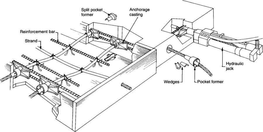
The non-jacking end of the strand may be bonded in concrete, or it may be fitted with a pre-locked anchorage which has also been cast in the concrete. The anchorage at the jacking end is called a live anchorage whereas the one at the non-jacking end is termed a dead anchorage. To allow the strand to stretch in the hardened concrete under the load applied by the jack, bond between the strand and concrete is prevented by a tube through which the strand passes. The tube, termed a duct or sheathing, may be a metal or plastic pipe, or it may consist of a plastic extrusion moulded directly on the rope. If extruded, the strand is injected with a rust-inhibiting grease. After stressing, the sheathing, if not of the extruded kind, is grouted with cement mortar using a mechanical pump.
The terms tendon and cable, are the general and interchangeable names for the high strength steel lengths used in post-tensioning—equivalent to reinforcement in reinforced concrete. A tendon may consist of individual wires, solid rods or ropes. It may contain one or more ropes or wires housed in a common sheathing.
Except in ground slabs, tendons do not run in straight lines. They are normally draped between supports with a shallow sag, just as a rope hangs when lightly stretched between two supports. The geometric shape of the tendon in elevation is called its profile; it is usually, but not necessarily, parabolic. At any point along its length, the vertical distance between the centroid of the concrete section and the centre of the tendon is called its eccentricity; by convention it is said to be positive when the tendon is below the section centroid.
The requirements for concrete, rod reinforcement and formwork for post-tensioning are similar to those for reinforced concrete, except for minor differences. Early strength of concrete is an advantage in post-tensioning; the quantity of rod reinforcement is much smaller; and the shuttering needs a hole in the vertical edge shutter at each jacking end of the tendon, and the anchorages need to be attached to the edge shutters. The differences in the materials, though minor, are discussed in detail in Chapter 2. Post-tensioning also needs stressing tendons to be made of high tensile strength; these and the associated hardware are briefly discussed in this chapter and in detail in Chapter 2.
The basic form of a post-tensioned floor is similar to that of a reinforced concrete floor. Slabs can be solid, ribbed or waffle; beams can be downstand, upstand or strips within the slab thickness.
1.2 Prestressing in principle
In reinforced concrete construction, the lack of strength of concrete in tension is compensated for by providing bonded steel reinforcement near the tension faces of the concrete section. The steel, being strong in tension, bears the tensile forces and the concrete takes the compressive forces. Under no-load condition the steel is unstressed; as a reinforced concrete member is loaded it deforms, inducing compressive and tensile stresses. The stresses in concrete and steel, therefore, vary with the load.
In prestressing, a permanent external axial force, of predetermined magnitude, is applied to the concrete member, which induces a compressive stress in the concrete section. When the service load is applied, the generated tensile stress has to overcome the compressive prestress before the concrete is driven into any tension. The tensile strength of concrete is, therefore, effectively enhanced. The prestressing force does not significantly change with the load within the serviceability limit. The principle is illustrated in Figure 1.2(a).
Figure 1.2 The principle of prestressing
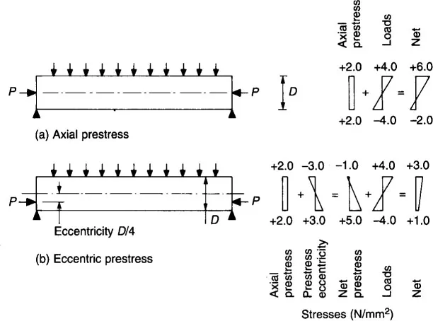
Consider a simple beam, required to carry a downward acting imposed load; at this stage, assume that the self-weight of the beam is negligible. An axial prestressing force is applied at the centroid of the section, which induces a uniform compressive stress across the section, Figure 1.2(a). At the top of the beam, the flexural compression is added to the prestress and the concrete on the compression face is subjected to the sum of the prestress and the flexural stress, i.e. the concrete has a higher compressive stress than it would have without the prestress. At the bottom of the beam, the flexural tension is in opposition to the compression from the prestress and, therefore, the stress in the concrete is lower than the tension it would have under flexure alone.
If the external force is applied eccentrically, as shown in Figure 1.2(b), then the compressive stress induced at the bottom of the section is higher for the same axial force. If the eccentricity is sufficiently large, the top of the beam develops a slight tension. When the imposed load is applied to such a beam, its top fibre is subjected to the difference between the flexural compression and the tension from prestress. Thus the flexural compression must overcome the prestress-induced tension before the concrete goes into compression. The bottom of the beam remains in compression.
An eccentrically applied force, therefore, increases the capacity of the section for flexural tension at the bottom and for compression at top. It is much more efficient than an axial prestress. The apparent enhancement in stress capacity of concrete allows a smaller concrete section to be used than is possible in reinforced concrete. Prestress is generally applied eccentrically, except in very special circumstances.
The advantage can perhaps be best illustrated by the numerical values shown in Figure 1.2. The applied load produces a compressive stress of + 4.0 N/mm2 at the top and a tensile stress of −4.0 N/mm2 at the bottom. With an axial prestress of 2.0 N/mm2 the combined net stresses would be + 6.0 N/mm2 and −2.0 N/mm2 at top and bottom respectively, Figure 1.2(a).
If the same prestressing force is applied eccentrically then a moment is induced, whose magnitude is the product of the prestressing force and its eccentricity. Assuming an eccentricity of one-quarter of the member depth, the moment produces flexural stresses of −3.0 N/mm2 tension at the top and + 3.0 N/mm2 compression at the bottom. These combine with the axial compression of +2.0N/mm2 to produce prestress stresses of −1.0 N/mm2 at top and + 5.0 N/mm2 at bottom. The final stresses, due to prestress and applied load, are now +3.0N/mm2 compression at top and + l.0 N/mm2 compression at bottom, Figure 1.2(b).
With a D/4 eccentricity (where D is the depth) the stress due to prestress alone has increased from + 2.0 N/mm2 to + 5.0 N/mm2 at bottom, the ratio of maximum to average stress being 2.5. This ratio is dependent on the shape of the section and the eccentricity. Ratios in the range of 2.5 to 4.0 are commonly achieved.
Note that with eccentric prestress both final stresses (top + 3.0 N/mm2 and bottom +1.0 N/mm2) are less than they would have been without prestress (+4.0 and −4.0 N/mm2 respectively). In fact, the bottom fibre is still in compression and, for a final tension of −2.0 N/mm2 as in the axially prestressed case, the prestressing force can be reduced by 60%.
In floors, the level of compression due to prestress is usually in the range of 1.0 to 5.0 N/mm2 (150 to 700 psi), the average being around 3.0 N/mm2 (450 psi). The lower levels of stress are generally used in ground slabs and the higher in post-tensioned beams. This range is quite low compared with that in, say, bridges where the average stress may be much higher, because of the longer spans and the higher loads.
1.3 Stress reversal
In continuous structures, if the self-weight of the floor is small compared with the applied loads or if there is a wide variation in span lengths, then it is possible for the load-induced stresses in a span to be reversed under a certain load combination; the stress at the bottom in the middle of the span may be compressive and at the top it may be tensile. In such a member in reinforced concrete, sufficient tension steel would be provided on each face to cope with the reversal. Reinforcement at each face would be designed independently of the reverse moment because the two conditions cannot exist simultaneously.
Consider what happens if the applied load is reversed in a prestressed member. Taking the example in Figure 1.2(b), assume that the reverse load produces a tension of −4.0 N/mm2 at the top and a compression of +4.0 N/mm2 at the bottom. The final stresses in this case would be as given in Table 1.1.
Table 1.1 Effect of load reversal
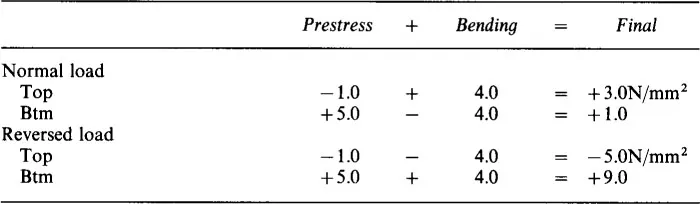
In the absence of any prestress, the flexural stresses for the reverse load (acting upwards) would be −4.0 N/mm2 at top and +4.0 N/mm2 at bottom; with prestress they are −5.0 and +9.0 N/mm2 respectively. Clearly, this prestressed member is worse off with the reverse loading.
The problem is caused by the high eccentricity, which induces a tension on the top face. This tension gets added to the flexural tension of the reverse load. With a lower eccentricity the stresses under the reversed load are also lower, though the stresses under the normal load would increase. In this example the reverse load is equal in magnitude to the normal load and so the best results would be obtained with an axially applied prestress. If the prestress produced a uniform compression of +2.0 N/mm2 over the whole section then the final stresses would be −2.0 and +6.0 N/mm2 in each case, as in Figure 1.2(a). This is an improvement on the eccentrically applied prestress but not an efficient use of materials.
This clearly illustrates that prestressing is not so effective when reversal of load is involved. Fortunately, load reversal seldom occurs in building floors and when it does, the dead load is usually sufficient either to keep the net load still acting downwards, or to greatly reduce the effect of the reverse loading. In continuous spans, of short length carrying heavy live loads, such as in warehouses, the dead load may not be large enough to avoid stress reversal and, therefore, reversal may be a critical condition. In such cases, a reduced eccentricity of prestress provides the better solution.
1.4 Tendons
In prestressed structures, the external prestressing force is generally applied by stretching steel rods, wires or ropes (strand) against the concrete section, which goes into compression. The high strength steel rods, wires, or strands are collectively called tendons or cables. In post-tensioned floors, however, use of strand is now almost universal.
The term strand can be rather confusing—it applies to the rope consisting of a number of individual wires wound together, it does not mean the individual wire comprising a rope. A typical strand consists of 7 wires wound into a rope; the commonly used sizes are nominal 13 mm and 15 mm (0.5 and 0.6 in) in diameter. The actual sizes and strand characteristics are given in Chapter 2.
In post-tensioning, because the prestress is applied after the concrete has gained sufficient strength, bond cannot be allowed to develop between the concrete and the tendons before stressing, and therefore, the tendons are housed in a bond-breaking duct or sheathing. More than one wire or strand may be housed in one common duct; the group of one or more is also called a tendon or cable.
The strand is similar to rod reinforcement with regard to its modulus of elasticity and coefficient of thermal expansion but it is about four times stronger than reinforcement steel. Strand may have an ultimate strength of 1860 N/mm2 (270 ksi) compared with 460 N/mm2 (67 ksi) for rod reinforcement. At service loads the strand may have a stress of ll00 N/mm2 (160 ksi) while rod reinforcement may carry only about 250 N/mm2 (36 ksi).
In addition to the tendons, some bonded rod reinforcement is also provided in post-tensioned floors—around the anchorages, in the slab as ties, as secondary reinforcement, or if needed to achieve the required ultimate strength.
The weight of steel (strands and rod reinforcement) required in a post-tensioned floor is typically only half, or less, of that needed...
Table of contents
- Cover
- Halftitle
- Title
- Copyright
- Contents
- Introduction
- Notations
- 1. The Basic Principles
- 2. Materials and Equipment
- 3. Slab Configuration
- 4. Planning a Structure
- 5. Tendon Profiles and Equivalent Loads
- 6. Flexure in the Serviceability State
- 7. Prestress Losses
- 8. Ultimate Flexural Strength
- 9. Deflection and Vibration
- 10. Shear
- 11. Slabs on Grade
- 12. Detailing
- 13. Site Activities and Demolition
- References
- Index
Frequently asked questions
Yes, you can cancel anytime from the Subscription tab in your account settings on the Perlego website. Your subscription will stay active until the end of your current billing period. Learn how to cancel your subscription
No, books cannot be downloaded as external files, such as PDFs, for use outside of Perlego. However, you can download books within the Perlego app for offline reading on mobile or tablet. Learn how to download books offline
Perlego offers two plans: Essential and Complete
- Essential is ideal for learners and professionals who enjoy exploring a wide range of subjects. Access the Essential Library with 800,000+ trusted titles and best-sellers across business, personal growth, and the humanities. Includes unlimited reading time and Standard Read Aloud voice.
- Complete: Perfect for advanced learners and researchers needing full, unrestricted access. Unlock 1.4M+ books across hundreds of subjects, including academic and specialized titles. The Complete Plan also includes advanced features like Premium Read Aloud and Research Assistant.
We are an online textbook subscription service, where you can get access to an entire online library for less than the price of a single book per month. With over 1 million books across 990+ topics, we’ve got you covered! Learn about our mission
Look out for the read-aloud symbol on your next book to see if you can listen to it. The read-aloud tool reads text aloud for you, highlighting the text as it is being read. You can pause it, speed it up and slow it down. Learn more about Read Aloud
Yes! You can use the Perlego app on both iOS and Android devices to read anytime, anywhere — even offline. Perfect for commutes or when you’re on the go.
Please note we cannot support devices running on iOS 13 and Android 7 or earlier. Learn more about using the app
Please note we cannot support devices running on iOS 13 and Android 7 or earlier. Learn more about using the app
Yes, you can access Post-Tensioned Concrete Floors by Martin Williams,Sami Khan in PDF and/or ePUB format, as well as other popular books in Technology & Engineering & Civil Engineering. We have over one million books available in our catalogue for you to explore.