Power transfer for large systems depends on high system voltages. The basics of high voltage laboratory techniques and phenomena, together with the principles governing the design of high voltage insulation, are covered in this book for students, utility engineers, designers and operators of high voltage equipment.
In this new edition the text has been entirely revised to reflect current practice. Major changes include coverage of the latest instrumentation, the use of electronegative gases such as sulfur hexafluoride, modern diagnostic techniques, and high voltage testing procedures with statistical approaches.
- A classic text on high voltage engineering
- Entirely revised to bring you up-to-date with current practice
- Benefit from expanded sections on testing and diagnostic techniques
1.1 Generation and transmission of electric energy
The potential benefits of electrical energy supplied to a number of consumers from a common generating system were recognized shortly after the development of the ‘dynamo’, commonly known as the generator.
The first public power station was put into service in 1882 in London (Holborn). Soon a number of other public supplies for electricity followed in other developed countries. The early systems produced direct ccurrent at low-voltage, but their service was limited to highly localized areas and were used mainly for electric lighting. The limitations of d.c. transmission at low-voltage became readily apparent. By 1890 the art in the development of an a.c. generator and transformer had been perfected to the point when a.c. supply was becoming common, displacing the earlier d.c. system. The first major a.c. power station was commissioned in 1890 at Deptford, supplying power to central London over a distance of 28 miles at 10 000 V. From the earliest ‘electricity’ days it was realized that to make full use of economic generation the transmission network must be tailored to production with increased interconnection for pooling of generation in an integrated system. In addition, the potential development of hydroelectric power and the need to carry that power over long distances to the centres of consumption were recognized.
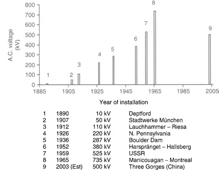
Power transfer for large systems, whether in the context of interconnection of large systems or bulk transfers, led engineers invariably to think in terms of high system voltages. Figure 1.1 lists some of the major a.c. transmission systems in chronological order of their installations, with tentative projections to the end of this century.
Figure 1.1 Major a.c. systems in chronological order of their installations
The electric power (P) transmitted on an overhead a.c. line increases approximately with the surge impedance loading or the square of the system’s operating voltage. Thus for a transmission line of surge impedance ZL (
250 Ω) at an operating voltage V, the power transfer capability is approximately P = V2/ZL, which for an overhead a.c. system leads to the following results:
The rapidly increasing transmission voltage level in recent decades is a result of the growing demand for electrical energy, coupled with the development of large hydroelectric power stations at sites far remote from centres of industrial activity and the need to transmit the energy over long distances to the centres. However, environmental concerns have imposed limitations on system expansion resulting in the need to better utilize existing transmission systems. This has led to the development of Flexible A.C. Transmission Systems (FACTS) which are based on newly developing high-power electronic devices such as GTOs and IGBTs. Examples of FACTS systems include Thyristor Controlled Series Capacitors and STATCOMS. The FACTS devices improve the utilization of a transmission system by increasing power transfer capability.
Although the majority of the world’s electric transmission is carried on a.c. systems, high-voltage direct current (HVDC) transmission by overhead lines, submarine cables, and back-to-back installations provides an attractive alternative for bulk power transfer. HVDC permits a higher power density on a given right-of-way as compared to a.c. transmission and thus helps the electric utilities in meeting the environmental requirements imposed on the transmission of electric power. HVDC also provides an attractive technical and economic solution for interconnecting asynchronous a.c. systems and for bulk power transfer requiring long cables.
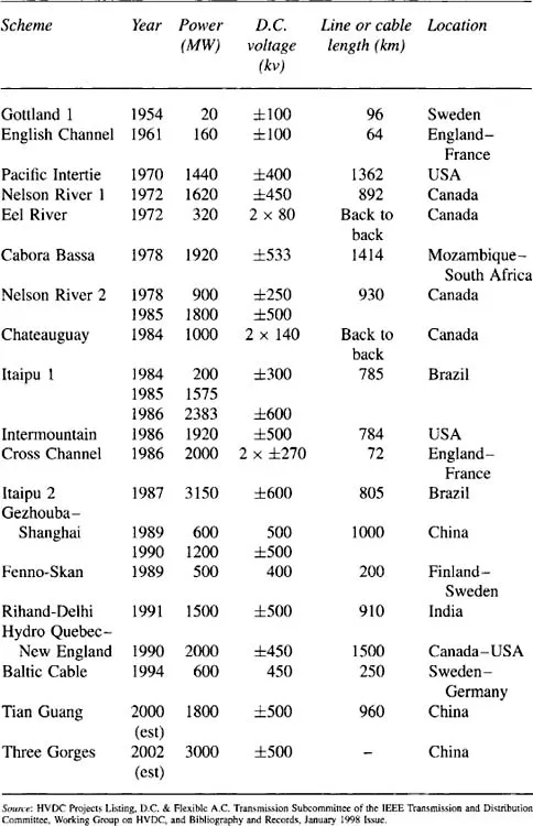
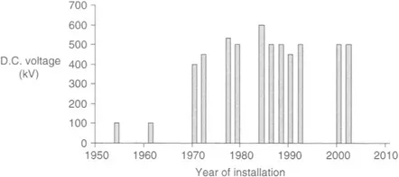
Table 1.1 summarizes a number of major HVDC schemes in order of their in-service dates. Figure 1.2 provides a graphic illustration of how HVDC transmission voltages have developed. As seen in Figure 1.2 the prevailing d.c. voltage for overhead line installations is 500 kV. This ‘settling’ of d.c. voltage has come about based on technical performance, power transfer requirements, environmental and economic considerations. Current trends indicate that d.c. voltage levels will not increase dramatically in the near future.
Table 1.1 Major HVDC schemes
Figure 1.2 Major d.c. systems in chronological order of their installations
1.2 Voltage stresses
Normal operating voltage does not severely stress the power system’s insulation and only in special circumstances, for example under pollution conditions, may operating voltages cause problems to external insulation. Nevertheless, the operating voltage determines the dimensions of the insulation which forms part of the generation, transmission and distribution equipment. The voltage stresses on power systems arise from various overvoltages. These may be of external or internal origin. External overvoltages are associated with lightning discharges and are not dependent on the voltage of the system. As a result, the importance of stresses produced by lightning decreases as the operating voltage increases. Internal overvoltages are generated by changes in the operating conditions of the system such as switching operations, a fault on the system or fluctuations in the load or generations.
Their magnitude depends on the rated voltage, the instance at which a change in operating conditions occurs, the complexity of the system and so on. Since the change in the system’s conditions is usually associated with switching operations, these overvoltages are generally referred to as switching overvoltages.
In designing the system’s insulation the two areas of specific importance are:
(i) determination of the voltage stresses which the insulation must withstand, and
(ii) determination of the response of the insulation when subjected to these voltage stresses.
The balance between the electric stresses on the insulation and the dielectric strength of this insulation falls within the framework of insulation coordination and will be discussed in Chapter 8 .
1.3 Testing voltages
Power systems equipment must withstand not only the rated voltage (Vm), which corresponds to the highest voltage of a particular system, but also overvoltages. Accordingly, it is necessary to test h.v. equipment during its development stage and prior to commissioning. The magnitude and type of test voltage varies with the rated voltage of a particular apparatus. The standard methods of measurement of high-voltage and the basic techniques for application to all types of apparatus for alternating voltages, direct voltages, switching impulse voltages and lightning impulse voltages are laid down in the relevant national and international standards.
1.3.1 Testing with power frequency voltages
To assess the ability of the apparatus’s insulation withstand under the system’s power frequency voltage the apparatus is subjected to the 1-minute test under 50 Hz or 60 Hz depending upon the country. The test voltage is set at a level higher than the expected working voltage in order to be able to simulate the stresses likely to be encountered over the years of service. For indoor installations the equipment tests are carried out under dry conditions only. For outdoor equipment tests may be required under conditions of standard rain as prescribed in the appropriate standards.
1.3.2 Testing with lightning impulse voltages
Lightning strokes terminating on transmission lines will induc...
Table of contents
Cover image
Title page
Table of Contents
Copyright
Preface to Second Edition
Preface to First Edition
Chapter 1: Introduction
Chapter 2: Generation of high voltages
Chapter 3: Measurement of high voltages
Chapter 4: Electrostatic fields and field stress control
Chapter 5: Electrical breakdown in gases
Chapter 6: Breakdown in solid and liquid dielectrics
Chapter 7: Non-destructive insulation test techniques
Chapter 8: Overvoltages, testing procedures and insulation coordination
Chapter 9: Design and testing of external insulation
Index
Frequently asked questions
Yes, you can cancel anytime from the Subscription tab in your account settings on the Perlego website. Your subscription will stay active until the end of your current billing period. Learn how to cancel your subscription
No, books cannot be downloaded as external files, such as PDFs, for use outside of Perlego. However, you can download books within the Perlego app for offline reading on mobile or tablet. Learn how to download books offline
Perlego offers two plans: Essential and Complete
Essential is ideal for learners and professionals who enjoy exploring a wide range of subjects. Access the Essential Library with 800,000+ trusted titles and best-sellers across business, personal growth, and the humanities. Includes unlimited reading time and Standard Read Aloud voice.
Complete: Perfect for advanced learners and researchers needing full, unrestricted access. Unlock 1.4M+ books across hundreds of subjects, including academic and specialized titles. The Complete Plan also includes advanced features like Premium Read Aloud and Research Assistant.
Both plans are available with monthly, semester, or annual billing cycles.
We are an online textbook subscription service, where you can get access to an entire online library for less than the price of a single book per month. With over 1 million books across 990+ topics, we’ve got you covered! Learn about our mission
Look out for the read-aloud symbol on your next book to see if you can listen to it. The read-aloud tool reads text aloud for you, highlighting the text as it is being read. You can pause it, speed it up and slow it down. Learn more about Read Aloud
Yes! You can use the Perlego app on both iOS and Android devices to read anytime, anywhere — even offline. Perfect for commutes or when you’re on the go. Please note we cannot support devices running on iOS 13 and Android 7 or earlier. Learn more about using the app
Yes, you can access High Voltage Engineering Fundamentals by John Kuffel,Peter Kuffel in PDF and/or ePUB format, as well as other popular books in Technology & Engineering & Electrical Engineering & Telecommunications. We have over one million books available in our catalogue for you to explore.