- 700 pages
- English
- ePUB (mobile friendly)
- Available on iOS & Android
eBook - ePub
Major Process Equipment Maintenance and Repair
About this book
This updated edition is an invaluable source of practical cost-effective maintenance, repair, installation, and field verification procedures for machinery engineers. It is filled with step-by-step instructions and quick-reference checklists that describe preventive and predictive maintenance for major process units such as vertical, horizontal, reciprocating, and liquid ring vacuum pumps, fans and blowers, compressors, turboexpanders, turbines, and more. Also included are sections on machinery protection, storage, lubrication, and periodic monitoring. A new section examines centrifugal pumps and explains how and why they continue to fail. More new information focuses on maintenance for aircraft derivative gas turbines. This revised edition gives special attention throughout to maintenance and repair procedures needed to ensure efficiency, performance, and long life.
Trusted by 375,005 students
Access to over 1.5 million titles for a fair monthly price.
Study more efficiently using our study tools.
Information
Part I
Installation and Repair of Major Process Equipment
Chapter 1
Installation, Maintenance, and Repair of Horizontal Pumps
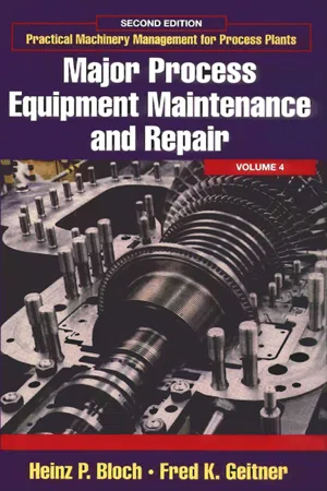
The most common centrifugal pump in the petrochemical industry is the horizontal single stage process pump. This pump has many different external designs. Perhaps the most common is the end suction top discharge design shown in Figure 1-1.
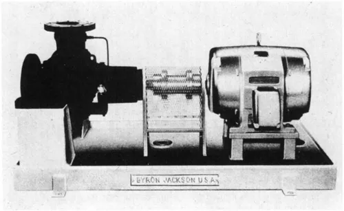
Figure 1-1 Horizontal single stage process pump to API (American Petroleum Institute) Standard. (Courtesy Byron Jackson.)
There are many features about this pump that make it adaptable for most applications. Designs can be small and inexpensive, or they can be designs that meet API 601* standards as well as with ANSI** specifications. The top centerline discharge provides excellent stability when subjected to piping stresses and high temperatures. Larger pump models incorporate a double volute internal passageway that helps to balance radial loading on the impeller. This pump design has a vertical radial split casing with centerline supports and an overhung impeller mounted on a shaft supported by bearings. By changing impeller designs, this pump can be adapted to all kinds of product applications from light hydrocarbons to slurries.
ANSI pumps differ from API* designs as follows: They are chemical process pumps designed in accordance with ANSI/ASME B73.1M-1991 (horizontal end suction) and ANSI/ASME B73.2M-1991 (vertical inline). ANSI pumps (Figure 1-2) are generally supplied with open impellers.
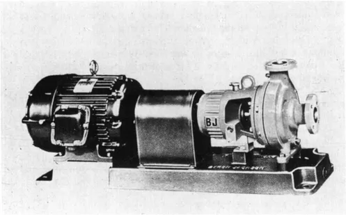
Figure 1-2 Typical ANSI horizontal process pump with foot mounted casing. (Courtesy Byron Jackon.)
Temperatures are usually limited to 300°F and pressures to 300 psi maximum, depending on the material and flange type. Capacity ranges from 0-5,000 gpm, and materials are mostly ductile iron cases and impellers. Often stainless steel is used together with 316 stainless steel shaft sleeves. Pump suction and discharge will normally have 150 lb raised face flanges.
Mechanical seals provided in ANSI pumps are normally unbalanced, single inside, but single outside seals are also quite common. Face materials are often carbon versus ceramic or tungsten carbide. Other materials can be substituted where applicable. Seal flush is usually configured as recirculation from pump discharge.
Motors: TEFC (totally enclosed fan cooled) 460 volt (560 in Canada), three phase at 60 Hertz are standard drivers for North American applications.
Base Plates: Normally fabricated from steel plate with smaller base plates cast. Pump and motor are mounted on the base plate and connected with a coupling. For maintenance and repair work the coupling will have to be removed and the pump internals can be removed from the pump case without disturbing the piping.
ANSI vertical in-line pumps are made in three basic designs: Style “A” is identified by the rigid spacer coupling which connects the pump stub shaft to the motor shaft. This design allows pump mechanical seal and impeller to be removed without disturbing the motor or pump flanges. All radial and thrust loads are transferred to the motor bearings. This style of pump is shown in Figure 1-3.
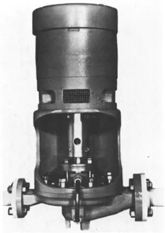
Figure 1-3 Vertical inline centrifugal pump. Rigid coupling, impeller, stuffing box and mechanical seal can be removed without disturbing motor and piping. (Courtesy Union Pump (Canada) Ltd.)
Style “B” consists of a horizontal pump mounted in vertical position with a special in-line casing and motor support. The motor is mounted on top of the support and is connected to the pump with a flexible coupling that allows pull out of pump without disturbing the piping. The advantage of this pump design is that radial and thrust conditions are controlled by the pump bearings rather than the motor bearings. Also some parts are interchangeable with horizontal models. Figure 1-4 shows this style of pump.
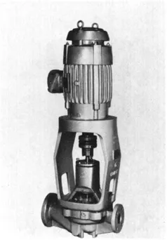
Figure 1-4 Vertical inline pump. Pump shaft is supported with its own independent bearings which also protect against radial thrust and shaft run-out. Source: Duriron Co.
Style “C” is the close-coupled design. The motor shaft is extended, and the impeller and mechanical seal mounted on it (no separate pump shaft needed). One disadvantage with this is that if anything goes wrong with the seal or pump, it can also cause damage to the motor. This design (see Figure 1-5) is being used less and less. API vertical in-line pumps will be discussed later.
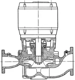
Figure 1-5 Vertical inline pump, close coupled design. Impeller and mechanical seal are mounted on motor shaft.
API (American Petroleum Institute) style pumps are designed for petrochemical services in accordance with API Standard 610. API standards define minimum requirements for pumps in heavy duty hydrocarbon service.
API pumps are generally specified in steel or noncorrosive materials with 300 lb raised face (RF) flanges. The pump casings are available with centerline supports rather than foot supports to reduce alignment distortion at high temperatures. The pressure limitations are at approximately 700 PSI with a maximum temperature of 850°F. API pumps are required to have closed impellers with case and impeller wear rings.
The base plate and motor requirements will be the same as the ANSI pumps, although the procurement of sturdier baseplates is advisable.
Principles of Installation of Pumps and Drivers*
The correct installation of pumps and drivers is an often overlooked requirement. Incorrect installation indirectly costs millions of dollars a year in increased maintenance and lost production due to premature equipment failure.
This segment of our text provides a set of guidelines that will result in a good pump installation. While centered around a typical single-stage, overhung, centrifugal pump, and a motor driver, it can easily be adapted to all types of machinery—the principles are the same. And, while these guidelines prescribe the minimum requirements to be performed by the installing agency, any specific instructions provided by the equipment manufacturer should also be observed. Conflicts should be resolved prior to in...
Table of contents
- Cover image
- Title page
- Table of Contents
- Front Matter
- Copyright page
- Acknowledgments
- Foreword
- Part I: Installation and Repair of Major Process Equipment
- Part II: Maintenance for Power Generation and Transmission
- Part III: General Preventive and Predictive Maintenance
- Index
- About the Authors
Frequently asked questions
Yes, you can cancel anytime from the Subscription tab in your account settings on the Perlego website. Your subscription will stay active until the end of your current billing period. Learn how to cancel your subscription
No, books cannot be downloaded as external files, such as PDFs, for use outside of Perlego. However, you can download books within the Perlego app for offline reading on mobile or tablet. Learn how to download books offline
Perlego offers two plans: Essential and Complete
- Essential is ideal for learners and professionals who enjoy exploring a wide range of subjects. Access the Essential Library with 800,000+ trusted titles and best-sellers across business, personal growth, and the humanities. Includes unlimited reading time and Standard Read Aloud voice.
- Complete: Perfect for advanced learners and researchers needing full, unrestricted access. Unlock 1.5M+ books across hundreds of subjects, including academic and specialized titles. The Complete Plan also includes advanced features like Premium Read Aloud and Research Assistant.
We are an online textbook subscription service, where you can get access to an entire online library for less than the price of a single book per month. With over 1.5 million books across 990+ topics, we’ve got you covered! Learn about our mission
Look out for the read-aloud symbol on your next book to see if you can listen to it. The read-aloud tool reads text aloud for you, highlighting the text as it is being read. You can pause it, speed it up and slow it down. Learn more about Read Aloud
Yes! You can use the Perlego app on both iOS and Android devices to read anytime, anywhere — even offline. Perfect for commutes or when you’re on the go.
Please note we cannot support devices running on iOS 13 and Android 7 or earlier. Learn more about using the app
Please note we cannot support devices running on iOS 13 and Android 7 or earlier. Learn more about using the app
Yes, you can access Major Process Equipment Maintenance and Repair by Heinz P. Bloch,Fred K. Geitner in PDF and/or ePUB format, as well as other popular books in Biowissenschaften & Gartenbau. We have over 1.5 million books available in our catalogue for you to explore.