- 288 pages
- English
- ePUB (mobile friendly)
- Available on iOS & Android
eBook - ePub
About this book
Heat Pipes, Sixth Edition, takes a highly practical approach to the design and selection of heat pipes, making it an essential guide for practicing engineers and an ideal text for postgraduate students.This new edition has been revised to include new information on the underlying theory of heat pipes and heat transfer, and features fully updated applications, new data sections, and updated chapters on design and electronics cooling. The book is a useful reference for those with experience and an accessible introduction for those approaching the topic for the first time.
- Contains all information required to design and manufacture a heat pipe
- Suitable for use as a professional reference and graduate text
- Revised with greater coverage of key electronic cooling applications
Trusted by 375,005 students
Access to over 1.5 million titles for a fair monthly price.
Study more efficiently using our study tools.
Information
Chapter 1
Historical development
Heat pipes are not new, but many variants and applications are. A historical perspective is valuable in assessing a technology in bringing to the fore aspects of the technology that may have become neglected or forgotten. This chapter attempts to do that, starting with the Perkins tube and moving to early wicked structures before highlighting some current important developments, such as the interest in nanofluids and more environmentally friendly working fluids. The heat pipe is adapting to new challenges.
Keywords
History; Perkins tube; patents; new concepts
The heat pipe differs from the thermosyphon by virtue of its ability to transport heat against gravity by an evaporation–condensation cycle. It is, however, important to realise that many heat pipe applications do not need to rely on this feature, and the Perkins tube, which predates the heat pipe by several decades and is basically a form of thermosyphon, is still used in heat transfer equipment. The Perkins tube must therefore be regarded as an essential part of the history of the heat pipe.
1.1 The perkins tube
Angier March Perkins was born in Massachusetts, USA, at the end of the eighteenth century, the son of Jacob Perkins, also an engineer [1]. In 1827, A.M. Perkins came to England, where he subsequently carried out much of his development work on boilers and other heat distribution systems. The work on the Perkins tube, which is a two-phase flow device, is attributed in the form of a patent to Ludlow Patton Perkins, the son of A.M. Perkins, in the mid-nineteenth century. A.M. Perkins, however, also worked on single-phase heat distribution systems, with some considerable success, and although the chronological development has been somewhat difficult to follow from the papers available, the single-phase systems preceded the Perkins tube, and some historical notes on both systems seem appropriate.
The catalogue describing the products of A.M. Perkins & Sons Ltd, published in 1898, states that in 1831 A.M. Perkins took out his first patent for what is known as ‘Perkins’ system of heating by small bore wrought iron pipes. This system is basically a hermetic tube boiler in which water is circulated in tubes (in single phase and at high pressure) between the furnace and the steam drum, providing an indirect heating system. The boiler using hermetic tubes, described in UK Patent No. 6146, was produced for over 100 years on a commercial scale. The specification describes this closed cycle hot water heater as adapted for sugar making and refining evaporators, steam boilers and also for various processes requiring molten metals for alloying or working of other metals at high temperatures, suggesting that the tubes in the Perkins system operate with high-pressure hot water at temperatures well in excess of 150°C.
The principle of the ‘ever full’ water boiler, as devised in the United States by Jacob Perkins to prevent the formation of a film of bubbles on the inner wall of the heat input section of the tubes, is applied as described in the above patent.
As water expands about one-twentieth of its bulk being converted into steam, I provide about double that extra space in the ‘expansion tube’ which is fitted with a removable air plug to allow the escape of air when the boiler is being filled. With this space for the expansion of the heated water the boiler is completely filled, and will at all times be kept in constant contact with the metal, however high the degree of heat such apparatus may be submitted to; and at the same time there will be no danger of bursting the apparatus with the provision of the sufficient space as named for the expansion of the water.
In 1839 most of the well-known forms of A.M. Perkins hot water hermetic heating tubes were patented in UK Patent No. 8311, and in that year a new invention, a concentric tube boiler, was revealed. The hot water closed circuit heating tubes in the concentric tube system were fork-ended and dipped into two or more steam generation tubes. These resembled superheater elements as applied on steam locomotives and a large boiler operating on this principle would consist of many large firetubes, all sealed off at one end and traversed by the inner hot water tubes, connected up externally by U bends. This proved to be the most rapid producer of superheated steam manufactured by the Perkins Company and was even used as the basis for a steam-actuated rapid firing machine gun, offered to the US Federal Government at the time of the Civil War. Although not used, they were ‘guaranteed to equal the efficiency of the best Minie rifles of that day, but at a much lower cost for coal than for gun powder’. The system was, however, used in marine engines, ‘… it gives a surprising economy of fuel and a rapid generation, with lightness and compactness of form; and a uniform pressure of from 200 lbs to 800 lbs per sq. in., may be obtained by its use’.
Returning to the Perkins hermetic tube single-phase water circulating boiler, as illustrated in Fig. 1.1, some catalogues describe these units as operating at pressures up to 4000 psi and being pressure-tested in excess of 11 000 psi. Operators were quick to praise the cleanliness, both inside and outside, of the hermetic tubes after prolonged use.
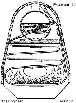
Figure 1.1 Perkins boiler.
The first use of the Perkins tube, that is one containing only a small quantity of water and operating on a two-phase cycle, is described in a patent by Jacob Perkins (UK Patent No. 7059, April 1936). The general description is as follows [2]:
One end of each tube projects downwards into the fire or flue and the other part extends up into the water of the boiler; each tube is hermetically closed to prevent escape of steam. There will be no incrustation of the interior of the tubes and the heat from the furnace will be quickly transmitted upwards. The interior surfaces of the tubes will not be liable to scaleage or oxidation, which will, of course, tend much to preserve the boiler so constructed. These tubes are each one to have a small quantity of water depending upon the degree of pressure required by the engine; and I recommend that the density of the steam in the tubes should be somewhat more than that intended to be produced in the boiler, and, for steam and other boilers under the atmospheric pressure, that the quantity of water to be applied in each tube is to be about 1:1800 part of the capacity of the tube; for a pressure of 2 atm to be two 1:1800 parts; for 3 atm, three 1:1800 parts, and so on, for greater or less degrees of pressure, and by which means the tubes of the boiler when at work will be pervaded with steam, and any additional heat applied thereto will quickly rise to the upper parts of the tubes and be given off to the surrounding water contained in the boiler – for steam already saturated with heat requires no more (longer) to keep the atoms of water in their expanded state, consequently becomes a most useful means of transmitting heat from the furnace to the water of the boiler.
The earliest applications for this type of tube were in locomotive boilers and in locomotive fire box superheaters (in France in 1863). Again, as with the single-phase sealed system, the cleanliness of the tubes was given prominent treatment in many papers on the subject. At the Institution of Civil Engineers in February 1837, Perkins stated that following a 7-month life test on such a boiler tube under representative operating conditions, there was no leakage or incrustation, no deposit of any kind occurring within the tube.
1.2 Patents
Reference has already been made to several patents taken by A.M. Perkins and J. Perkins on hermetic single-phase and two-phase heating tubes, normally for boiler applications. The most interesting patent, however, which relates to improvements in the basic Perkins tube, is UK Patent No. 22272, dated 1892, and granted to L.P. Perkins and W.E. Buck: ‘Improvements in Devices for the Diffusion or Transference of Heat’ [3].
The basic claim, with a considerable number of modifications and details referring to fluid inventory and application, is for a closed tube or tubes of suitable form or material, partially filled with a liquid. While water is given as one specific working fluid, the patent covers the use of antifreeze-type fluids as well as those having a higher boiling point than water.
It is obvious that previous work on the Perkins tube had revealed that purging of the tubes of air, possibly by boiling off a quantity of the working fluid prior to sealing, was desirable, as Perkins and Buck indicate that this should be done for optimum operation at low temperatures (hence low internal pressures) and when it is necessary to transmit heat as rapidly as possible at high temperatures.
Safety and optimum performance were also considered in the patent, where reference is made to the use of ‘suitable stops and guides’ to ensure that tubes refitted after external cleaning were inserted at the correct angle and with the specified amount of evaporator section exposed to the heat source (normally an oil, coal or gas burner). Some form of entrainment had also probably occurred in the original straight Perkins tube, particularly when transferring heat over considerable distances. As a means of overcoming this limitation, the patent provides U bends so that the condensate return occurs in the lower portion of the tube, vapour flow to the heat sink taking place in the upper part.
Applications cited included heating of greenhouses, rooms, vehicles, dryers, and as a means of preventing condensation on shop windows, the tubes providing a warm convection current up the inner face of the window. Indirect heating of bulk tanks of liquid is also suggested. The use of the device as a heat removal system for cooling dairy products, chemicals and heat exchanging with the cooling water of gas engines is also proposed, as its use in waste heat recovery, the heat being recovered from the exhaust gases from blast furnaces and other similar apparatus, and used to preheat incoming air.
On this and other air/gas heating applications of the Perkins tube, the inventors have neglected to include the use of external finning on the tubes to improve the tube-to-gas heat transfer. Although not referring to the device as a Perkins tube, such modifications were proposed by F.W. Gay in US Patent No. 1725906, dated 27 August 1929, in which a number of finned Perkins tubes or thermosyphons are arranged as in the conventional gas/gas heat pipe heat exchanger, with the evaporator sections located vertically below the condensers, a plate sealing the passage between the exhaust and inlet air ducts, as shown in Fig. 1.2. Working fluids proposed include methanol, water and mercury, depending upon the likely exhaust gas temperatures.
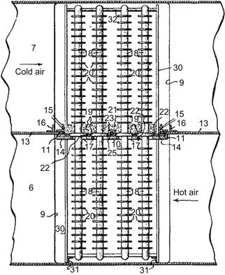
Figure 1.2 Thermosyphon heat exchanger proposed by F.W. Gay.
1.3 The baker’s oven
The main use of the Perkins tube was in baking ovens. One of the earliest forms of baking ovens to which the Perkins tube principle was applied was a portable bread oven supplied to the British army in the nineteenth century. In common with static ovens employing the Perkins tube, the firing was carried out remote from the baking chamber, the heat being transferred from the flames to the chamber by the vapour contained within the tubes. The oven operated at about 210°C, and it was claimed that the fuel savings using this type of heating were such that only 25% of the fuel typically consumed by conventional baking ovens was required [4].
A more detailed account of the baking oven is given in Ref. [5]. This paper, published in 1960 by the Institution of Mechanical Engineers, is par...
Table of contents
- Cover image
- Title page
- Table of Contents
- Copyright
- Dedication
- Preface to sixth edition
- Preface to first edition
- Acknowledgements
- Nomenclature
- Introduction
- Chapter 1. Historical development
- Chapter 2. Heat transfer and fluid flow theory
- Chapter 3. Heat pipe components and materials
- Chapter 4. Design guide
- Chapter 5. Heat pipe manufacture and testing
- Chapter 6. Special types of heat pipe
- Chapter 7. Applications of the heat pipe
- Chapter 8. Cooling of electronic components
- Appendix 1. Working fluid properties
- Appendix 2. Thermal conductivity of heat pipe container and wick materials
- Appendix 3. A selection of heat-pipe-related web sites
- Appendix 4. Conversion factors
- Index
Frequently asked questions
Yes, you can cancel anytime from the Subscription tab in your account settings on the Perlego website. Your subscription will stay active until the end of your current billing period. Learn how to cancel your subscription
No, books cannot be downloaded as external files, such as PDFs, for use outside of Perlego. However, you can download books within the Perlego app for offline reading on mobile or tablet. Learn how to download books offline
We are an online textbook subscription service, where you can get access to an entire online library for less than the price of a single book per month. With over 1.5 million books across 990+ topics, we’ve got you covered! Learn about our mission
Look out for the read-aloud symbol on your next book to see if you can listen to it. The read-aloud tool reads text aloud for you, highlighting the text as it is being read. You can pause it, speed it up and slow it down. Learn more about Read Aloud
Yes! You can use the Perlego app on both iOS and Android devices to read anytime, anywhere — even offline. Perfect for commutes or when you’re on the go.
Please note we cannot support devices running on iOS 13 and Android 7 or earlier. Learn more about using the app
Please note we cannot support devices running on iOS 13 and Android 7 or earlier. Learn more about using the app
Yes, you can access Heat Pipes by David Reay,Ryan McGlen,Peter Kew in PDF and/or ePUB format, as well as other popular books in Technology & Engineering & Thermodynamics. We have over 1.5 million books available in our catalogue for you to explore.