
eBook - ePub
Multilevel Inverters
Conventional and Emerging Topologies and Their Control
- 228 pages
- English
- ePUB (mobile friendly)
- Available on iOS & Android
eBook - ePub
Multilevel Inverters
Conventional and Emerging Topologies and Their Control
About this book
Multilevel Inverters: Conventional and Emerging Topologies and Their Control is written with two primary objectives: (a) explanation of fundamentals of multilevel inverters (MLIs) with reference to the general philosophy of power electronics; and (b) enabling the reader to systematically analyze a given topology with the possibility of contributing towards the ongoing evolution of topologies. The authors also present an updated status of current research in the field of MLIs with an emphasis on the evolution of newer topologies. In addition, the work includes a universal control scheme, with which any given topology can be modulated. Extensive qualitative and quantitative evaluations of emerging topologies give researchers and industry professionals suitable solutions for specific applications with a systematic presentation of software-based modeling and simulation, and an exploration of key issues.
Topics covered also include power distribution among sources, voltage balancing, optimization switching frequency and asymmetric source configuration. This valuable reference further provides tools to model and simulate conventional and emerging topologies using MATLAB®/Simulink® and discusses execution of experimental set-up using popular interfacing tools.
The book includes a Foreword by Dr. Frede Blaabjerg, Fellow IEEE, Professor and VILLUM Investigator, Aalborg University, Denmark.
- Includes a universal control scheme to help the reader learn the control of existing topologies and those which can be proposed in the future
- Presents three new topologies. Systematic development of these topologies and subsequent simulation and experimental studies exemplify an approach to the development of newer topologies and verification of their working and experimental verification.
- Contains a systematic and step-by-step approach to modelling and simulating various topologies designed to effectively employ low-power applications
Trusted by 375,005 students
Access to over 1.5 million titles for a fair monthly price.
Study more efficiently using our study tools.
Information
Chapter 1
Basics of Inverters
Abstract
In this chapter, fundamental concepts related to power electronics and inverters are discussed. Popular terminology is defined so that understanding multilevel inverters becomes much easier.
Keywords
Converters; electricity; energy; inverters; voltage
1.1 Introduction
While the demand for electrical energy continues to grow throughout the world, it is estimated that 100% of electrical energy will flow through power electronics, especially in developed countries [1]. It is anticipated that the role of power electronics in this era will be as crucial as that of computers and communication technologies. Power electronics has changed the face of electrical engineering. Applications of power electronics include regulated power supplies, uninterruptible power supplies (UPS), electrochemical processes, heating and lighting control, welding, reactive power compensation, flexible AC transmission systems, active filters, energy storage, motor drives, and so on. Of all power electronics converters, DC to AC converters (i.e. “inverters”) are most widely employed in the modern set-up of electric power generation, transmission, distribution, utilization, and protection.
This chapter deals with the fundamentals of inverters, however before that, there is a discussion on the power electronics technology. Throughout this book, concepts are discussed mainly in the context of voltage source inverters because the voltage-fed class of inverters is becoming universal, replacing the current-fed class [1]. While you might already have a good understanding of inverters, we would still recommend you read this chapter. This chapter serves as the base for building up a case for multilevel inverters. It will help you understand and appreciate the concept behind multilevel inverters from various angles. Moreover, it will help you understand the popular terminology for multilevel inverters in research publications.
In addition to the basics of the so-called H-bridge inverter, we also discuss the philosophy behind waveform analysis and filtering needs. This discussion sets up the scene for the pulse-width modulation (PWM) technique. In the final part, power switch requirements are discussed for inverters in general. Some more specific cases in the context of multilevel inverters will be taken up in subsequent chapters.
1.2 Power Electronics as a Technology
The purpose of this section is to understand the philosophy of power electronics in a simplified manner. Once this philosophy is understood, it will be extremely easy to introduce and analyze various concepts related to inverters at this stage and those related to multilevel inverters at later stages.
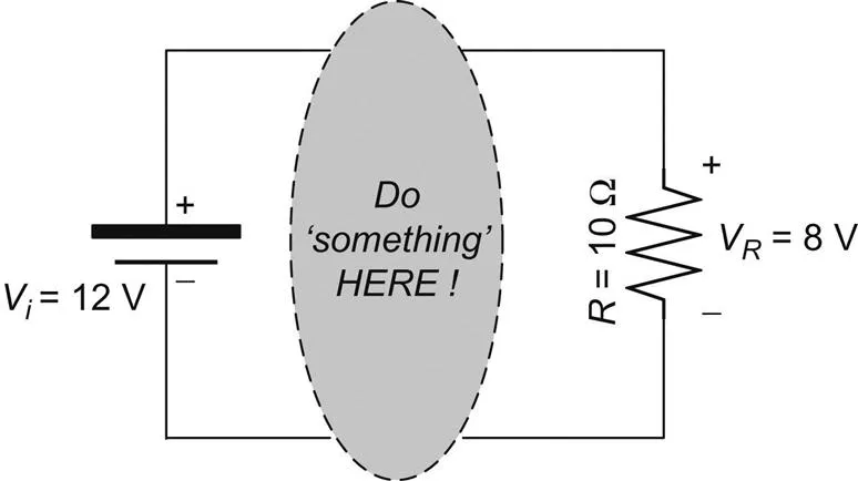
Before defining power electronics, let us consider a hypothetical problem (without considering practical application, as of now): you have a resistance of 10 Ω which is to be supplied with a voltage of 8 V, while you have a battery of 12 V at your disposal. What do you do? Well, you visualize the problem as shown in Fig. 1.1. You recognize that the battery (the “source”) is, of course, to be connected to the resistance (the “load”), but since the required voltage and the available voltage do not match, you need to do “something” in between! And that “something” should “step-down” the voltage from 12 to 8 V.
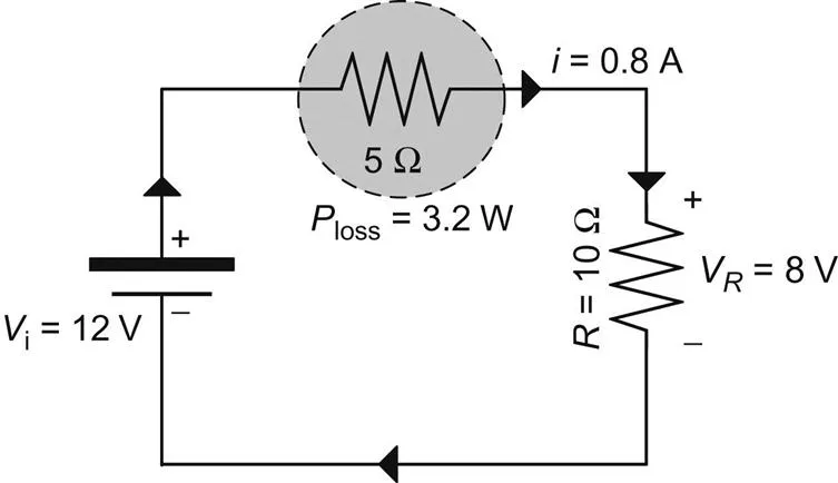
Conventional wisdom tells you to connect another resistance of 5 Ω “in between” and voila! You do get the required voltage at the load terminals, as shown in Fig. 1.2. But there is a catch. The 5 Ω resistance dissipates a power of 3.2 W, while the source delivers a power of 6.4 W. So, the power loss is 50% of delivered power!
So you now look for another solution which fulfills two requirements: it steps down voltage and it does so without any power loss (ideally). You connect a “switch S” in between the source and the load, as shown in Fig. 1.3A. And, you repeatedly operate the switch S in ON and OFF states. When S is ON, the instantaneous voltage vR(t) across the load is 12 V and when S is OFF, vR(t) is 0 V. These modes are shown in Fig. 1.3B and C, respectively. Your logic of doing so is simple: you are controlling the “average” voltage across the load. That is, if you keep S ON for a time duration T, then next you keep it OFF for a duration T/2 and you keep repeating it. You get a voltage waveform across the load resistance as shown in Fig. 1.3D and you calculate the average value of voltage to be 8 V (=VR)! Also, when ON, the switch carries a current of 1.2 A but the voltage...
Table of contents
- Cover image
- Title page
- Table of Contents
- Copyright
- Dedication
- Foreword
- About the Authors
- Preface
- Acknowledgments
- Chapter 1. Basics of Inverters
- Chapter 2. Basics of Multilevel Inverters
- Chapter 3. Advent of New Topologies
- Chapter 4. Universal Control Scheme with Voltage-Level-Based Methods
- Chapter 5. Multilevel Inverter Based on Bridge-Type Connected Sources
- Chapter 6. Cross-Connected Sources-Based Multilevel Inverter
- Chapter 7. Comparison of Multilevel Inverter Topologies
- Index
Frequently asked questions
Yes, you can cancel anytime from the Subscription tab in your account settings on the Perlego website. Your subscription will stay active until the end of your current billing period. Learn how to cancel your subscription
No, books cannot be downloaded as external files, such as PDFs, for use outside of Perlego. However, you can download books within the Perlego app for offline reading on mobile or tablet. Learn how to download books offline
Perlego offers two plans: Essential and Complete
- Essential is ideal for learners and professionals who enjoy exploring a wide range of subjects. Access the Essential Library with 800,000+ trusted titles and best-sellers across business, personal growth, and the humanities. Includes unlimited reading time and Standard Read Aloud voice.
- Complete: Perfect for advanced learners and researchers needing full, unrestricted access. Unlock 1.5M+ books across hundreds of subjects, including academic and specialized titles. The Complete Plan also includes advanced features like Premium Read Aloud and Research Assistant.
We are an online textbook subscription service, where you can get access to an entire online library for less than the price of a single book per month. With over 1.5 million books across 990+ topics, we’ve got you covered! Learn about our mission
Look out for the read-aloud symbol on your next book to see if you can listen to it. The read-aloud tool reads text aloud for you, highlighting the text as it is being read. You can pause it, speed it up and slow it down. Learn more about Read Aloud
Yes! You can use the Perlego app on both iOS and Android devices to read anytime, anywhere — even offline. Perfect for commutes or when you’re on the go.
Please note we cannot support devices running on iOS 13 and Android 7 or earlier. Learn more about using the app
Please note we cannot support devices running on iOS 13 and Android 7 or earlier. Learn more about using the app
Yes, you can access Multilevel Inverters by Krishna Kumar Gupta,Pallavee Bhatnagar in PDF and/or ePUB format, as well as other popular books in Technology & Engineering & Economic Theory. We have over 1.5 million books available in our catalogue for you to explore.