- 464 pages
- English
- ePUB (mobile friendly)
- Available on iOS & Android
eBook - ePub
About this book
Written for practicing engineers and students alike, this book emphasizes the role of finite element modeling and simulation in the engineering design process. It provides the necessary theories and techniques of the FEM in a concise and easy-to-understand format and applies the techniques to civil, mechanical, and aerospace problems. Updated throughout for current developments in FEM and FEM software, the book also includes case studies, diagrams, illustrations, and tables to help demonstrate the material.
- Plentiful diagrams, illustrations and tables demonstrate the material
- Covers modeling techniques that predict how components will operate and tolerate loads, stresses and strains in reality
- Full set of PowerPoint presentation slides that illustrate and support the book, available on a companion website
Tools to learn more effectively

Saving Books

Keyword Search

Annotating Text

Listen to it instead
Information
Chapter 1
Computational Modeling
1.1 Introduction
The Finite Element Method (FEM) has developed into a key indispensable technology in the modeling and simulation of advanced engineering systems in various fields like housing, transportation, communications, and so on. In building an advanced engineering system, engineers and designers go through a sophisticated process of modeling, simulation, visualization, analysis, design, prototyping, testing, and lastly, fabrication. More often than not, much work is involved before the fabrication of the final product or system. This is to ensure the workability of the finished product, as well as for cost effectiveness in the manufacturing process. This process is illustrated as a flowchart in Figure 1.1. It is often iterative in nature, meaning that some of the procedures are repeated based on the results obtained at a current stage, so as to achieve an optimal performance at the lowest cost for the system to be built. Therefore, techniques related to modeling and simulation in a rapid and effective way play an increasingly important role, and the FEM becomes very much a standard tool in any major development of a system or product.
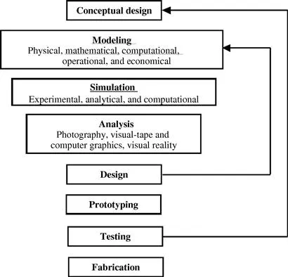
Figure 1.1 Processes leading to the fabrication of advanced engineering systems.
This book deals with topics related mainly to modeling and simulation, which are underscored in Figure 1.1. The focus will be on the techniques of physical, mathematical, and computational modeling, and other aspects of computational simulation. A good understanding of these techniques plays an important role in building an advanced engineering system in a rapid and cost-effective way.
So what is the FEM? The FEM was first used to solve problems of solid and structural analysis, and has since been applied to many problems like thermal analysis, fluid flow analysis, piezoelectric analysis, and many others. Basically, the analyst seeks to determine the distribution of some field variable, for example, the displacement in structural mechanics analysis, the temperature or heat flux in thermal analysis, the electrical charge in electrical analysis, and so on. The FEM is a numerical method that seeks an approximated solution of the distribution of field variables in the problem domain that is often difficult to obtain analytically. It is done by first dividing the problem domain into a number of small pieces called elements, often of simple geometry, as shown in Figures 1.2 and 1.3. Physical principles/laws are then applied to each small element. Figure 1.4 shows a schematic illustration of a distribution of a field, F(x), in one dimension that is approximated using the FEM. In this case, F(x) is a continuous function that is approximated using piecewise linear functions in an element. In this one-dimensional case, the ends of each element are termed nodes. The unknown variables in the FEM are simply the discrete values of the field variable at the nodes. Physical and mathematical principles are then followed to establish governing equations for each element, after which the elements are “tied” to one another to describe the distribution of the field in the entire geometry. This process leads to a set of linear algebraic simultaneous equations for the entire system that can be solved easily to yield the required field variable.
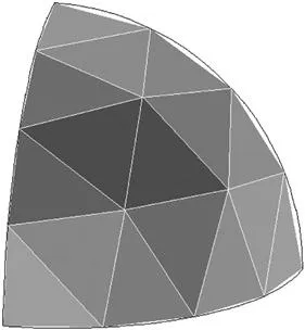
Figure 1.2 Hemispherical section discretized into several shell elements.
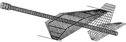
Figure 1.3 Mesh for the design of a scaled model of an aircraft for dynamic testing in the laboratory (Quek 1997–98).
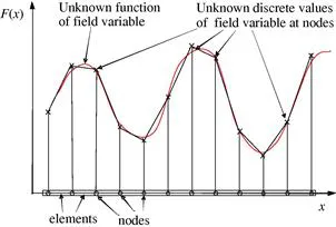
Figure 1.4 Finite element approximation for a one-dimensional case. A continuous function is approximated using piecewise linear functions in each sub-domain/element.
This book aims to bring across the various concepts, methods, and principles used in the formulation of FE equations in a manner that is easy to understand. Worked examples and case studies using the well-known commercial software package ABAQUS and ANSYS will be discussed, and effective techniques and procedures will be highlighted.
1.2 Physical problems in engineering
There are numerous physical problems in an engineering system. As mentioned earlier, although the FEM was initially used for solid and structural analysis, many other physical problems can be solved using the FEM. Mathematical models of the FEM have been formulated for the numerous physical phenomena that occur in engineering systems. Common physical problems solved using the standard FEM include:
• Mechanics for solids and structures
• Heat transfer
• Acoustics
• Fluid mechanics
• Combinations of the above
• Others
This book first focuses on the formulation of finite element equations for the mechanics of solids and structures, since that is what the FEM was initially designed for. FEM formulations for heat transfer problems are then described. Nevertheless, the conceptual understanding of the methodology of the FEM is the most important and will be emphasized in both solid mechanics and heat transfer problems. The application of the FEM to all other physical problems utilizes similar concepts.
Computer modeling using the FEM consists of the major steps discussed in the next section.
1.3 Computational modeling using FEM
The behavior of a physical phenomenon in a system depends upon the geometry or domain of the system, the property of the material or medium, and the boundary, initial, and loading conditions. For an engineering system, the geometry or domain can be very complex. Furthermore, the boundary and initial conditions can also be very complicated. It is therefore, in general, very difficult to solve the governing differential equation via analytical means. In practice, most of the problems are solved using numerical methods. Among these, the methods of domain discretization championed by the FEM are the most popular due to their reliability, practicality, versatility, and robustness.
The procedure of computational modeling using the FEM broadly consists of four steps:
• Modeling of the geometry
• Meshing (discretization)
• Specification of material property
• Specification of boundary, initial, and loading conditions
1.3.1 Modeling of the geometry
Most physical structures, components or domains are in general very complicated, and usually made up of multiple components. One can imagine the complexity that goes into making an automobile, an aircraft, an ocean-going vessel, and so on. It is therefore common, and often a good practice, to simplify parts of the geometry so that modeling is more manageable. The geometry and boundary of a structure can be made up of curved surfaces/lines, but as we perform FEM based modeling, it is important to bear in mind that the geometry is eventually represented by a collection of elements, and the curved lines/surfaces may be approximated by piecewise straight lines or flat surfaces, if these elements are assumed to be flat/straight pieces/segments (that is, linearity is assumed). Figure 1.2 shows an example of a curved boundary represented by the straight lines of the edges of triangular elements. The accuracy of the representation of the curved part, as in Figure 1.2, is controlled by the number of elements used. It is obvious that with more elements, the representation of the curved parts by straight edges would be smoother and more accurate. On the other hand, with more elements, longer computational time is required. Unfortunately, modelers often face constraints in terms of available computational resources and it is often necessary to limit the number of elements used in the model. As such, compromises are usually made in order to decide on an optimum number of elements used. These compromises usually result in the omission of fine details of the geometry unless very accurate results are required for those regions. The analysts will then have to interpret the results of the simulation with these geometric approximations in mind.
Depending on the software used, there are many ways to create a proper geometry in the computer for the FE mesh. Points can be created simply by keying in the coordinates. Lines and curves can be created by connecting the points or nodes. Surfaces can be created by connecting, rotating or translating the existing lines or curves. Solids can be created by various operations of connecting, rotating or translating the existing surfaces. Points, lines and curves, surfaces and solids can be translated, rotated or reflected to form new ones.
More often than not, the use of a graphic interface helps in the creation and manipulation of the geometrical objects on computers. There are numerous Computer Aided Design (CAD) software packages used for engineering design. These CAD packages can generate appropriate files containing the geometry of the designed engineering system and these files can then be read by modeling software packages, in which appropriate discretization of the geometry into elements can be carried out. However, in many cases, complex objects read directly from a CAD file may need to be modified and simplified before performing discretization. It may be worth mentioning that there are CAD packages which incorporate modeling and simulation packages, and these are useful for the rapid prototyping of new products.
While most modeling software packages try to make modeling a breeze by developing excellent user interfaces, it is equally important to have knowledge, experience, and good engineering judgment. This is what distinguishes a good modeler from one who is just proficient in using the software. For example, finely detailed geometrical features often only play an aesthetic role, and have negligible effects on the functional performance of the engineering system. These features can sometimes be omitted, ignored or simplified, but it takes good engineering judgment to decide if any geometrical assumptions/simplifications will have a negligible effect on the overall simulation results.
Possessing sufficient knowledge and engineering judgment enables one to recognize a physical component, and possibly simplify that component mathematically, so that modeling can be more effective. For example, a plate has three dimensions geometrically. The plate in the plate theory of mechanics is represented mathematically only in two dimensions (the reason for this will be elaborated in Chapter 2). Therefore the geometry of a “mechanics” plate is a two-dimensional flat surface. Plate elements will be used in meshing these surfaces. A similar situation can be found in shells. A physical beam also has three dimensions. The beam in ...
Table of contents
- Cover image
- Title page
- Table of Contents
- Copyright
- Dedication
- Biography
- Preface to the First Edition
- Chapter 1. Computational Modeling
- Chapter 2. Briefing on Mechanics for Solids and Structures
- Chapter 3. Fundamentals for Finite Element Method
- Chapter 4. FEM for Trusses
- Chapter 5. FEM for Beams
- Chapter 6. FEM for Frames
- Chapter 7. FEM for Two-Dimensional Solids
- Chapter 8. FEM for Plates and Shells
- Chapter 9. FEM for 3D Solid Elements
- Chapter 10. Special Purpose Elements
- Chapter 11. Modeling Techniques
- Chapter 12. FEM for Heat Transfer Problems
- Chapter 13. Using FEM Software Packages
- References
- Index
Frequently asked questions
Yes, you can cancel anytime from the Subscription tab in your account settings on the Perlego website. Your subscription will stay active until the end of your current billing period. Learn how to cancel your subscription
No, books cannot be downloaded as external files, such as PDFs, for use outside of Perlego. However, you can download books within the Perlego app for offline reading on mobile or tablet. Learn how to download books offline
Perlego offers two plans: Essential and Complete
- Essential is ideal for learners and professionals who enjoy exploring a wide range of subjects. Access the Essential Library with 800,000+ trusted titles and best-sellers across business, personal growth, and the humanities. Includes unlimited reading time and Standard Read Aloud voice.
- Complete: Perfect for advanced learners and researchers needing full, unrestricted access. Unlock 1.4M+ books across hundreds of subjects, including academic and specialized titles. The Complete Plan also includes advanced features like Premium Read Aloud and Research Assistant.
We are an online textbook subscription service, where you can get access to an entire online library for less than the price of a single book per month. With over 1 million books across 990+ topics, we’ve got you covered! Learn about our mission
Look out for the read-aloud symbol on your next book to see if you can listen to it. The read-aloud tool reads text aloud for you, highlighting the text as it is being read. You can pause it, speed it up and slow it down. Learn more about Read Aloud
Yes! You can use the Perlego app on both iOS and Android devices to read anytime, anywhere — even offline. Perfect for commutes or when you’re on the go.
Please note we cannot support devices running on iOS 13 and Android 7 or earlier. Learn more about using the app
Please note we cannot support devices running on iOS 13 and Android 7 or earlier. Learn more about using the app
Yes, you can access The Finite Element Method by G.R. Liu,S. S. Quek in PDF and/or ePUB format, as well as other popular books in Technology & Engineering & Mechanical Engineering. We have over one million books available in our catalogue for you to explore.