eBook - ePub
Tribological Processes in the Valve Train Systems with Lightweight Valves
New Research and Modelling
- 298 pages
- English
- ePUB (mobile friendly)
- Available on iOS & Android
eBook - ePub
Tribological Processes in the Valve Train Systems with Lightweight Valves
New Research and Modelling
About this book
Tribological Processes in Valvetrain Systems with Lightweight Valves: New Research and Modelling provides readers with the latest methodologies to reduce friction and wear in valvetrain systems—a severe problem for designers and manufacturers. The solution is achieved by identifying the tribological processes and phenomena in the friction nodes of lightweight valves made of titanium alloys and ceramics, both cam and camless driven.
The book provides a set of structured information on the current tribological problems in modern internal combustion engines—from an introduction to the valvetrain operation to the processes that produce wear in the components of the valvetrain. A valuable resource for teachers and students of mechanical or automotive engineering, as well as automotive manufacturers, automotive designers, and tuning engineers.
- Shows the tribological problems occurring in the guide-light valve-seat insert
- Combines numerical and experimental solutions of wear and friction processes in valvetrain systems
- Discusses various types of cam and camless drives the valves used in valve trains of internal combustion engines—both SI and CI
- Examines the materials used, protective layers and geometric parameters of lightweight valves, as well as mating guides and seat inserts
Trusted by 375,005 students
Access to over 1.5 million titles for a fair monthly price.
Study more efficiently using our study tools.
Information
Chapter 1
Introduction
Abstract
In the chapter the different solutions for obtaining the increased fuel economy and lower emissions are pointed, including variable valve control, exhaust gas recirculation, direct injection and hybridization of vehicles. The variable valve control system adds a few degrees of freedom to control the internal combustion engine. Increasing the speed of engine with cam or camless valve train requires a low weight of moving parts, like valves, to reduce inertia forces loading the timing and the power required to its drive. The change of valve material needs usually also changing the materials of guides and seat inserts, what influences the operation conditions, friction between mating elements and their wear intensity. Also the lubrication of contacts can be changed, and the possible solutions are shortly discussed. The approximate criterion for classifying valves as lightweight is also presented.
Keywords
solutions increasing fuel economy and lower emissions; variable valve control system; tribological problems related to lightweight valves; lubrication system changes; criterion for classifying valves as lightweight
In the current worldwide population of several million vehicles equipped with internal combustion engines, different solutions are employed to obtain increased fuel economy and lower emissions, which are necessary due to increasingly stringent environmental standards [1]. Some are well known, whereas others are still in development. Examples of such solutions include variable valve actuation (VVA), exhaust gas recirculation, direct injection, and hybridization of vehicles. The VVA system adds a few degrees of freedom to control the internal combustion engine.
Tribological processes that occur in the existing valve train with cam-driven valves are well known and described in the literature [2–4]. In current solutions of valve timing with cam drive, the steel valves are used in conjunction with seat inserts and guides of cast alloy. The operation is provided under conditions of mixed friction due to intentional limits on the amount of oil supplied to the contact zones of the valve stem, guide, and valve seats and seat insert. Extortions acting on elements of the guide–valve–seat insert set are repeatable and subject to duty cycle of the engine, applied geometry, and stiffness in the elements of the valve train. Variations in these conditions occur mainly during cold engine warm-up and are short-lived.
Increasing the speed of engines with a cam or camless valve train requires the moving parts, such as valves, to be lightweight to reduce inertia forces loading the timing and the power required to drive it.
A relatively new area of use of VVA engines is hybrid vehicles—electrical, with fuel cells, or pneumatic. In such vehicles, the engine can operate at the optimal operating point due to the load and speed. Due to the necessity for frequent engine shutdown, the VVA engine is best suited to operate in such conditions.
The introduction of new systems of control valves, including the VVA system, changes waveforms of load, relative velocity, and temperature characterizing operation of components of the guide–valve–seat insert system. This results in changes in courses of the resistance of motion in the valve stems against guides and wear intensity for components of those systems. Operational conditions of each controlled system and the type of drive valve are specific to each system because each system has its own unique dynamics based on the algorithm used and the control and drive components. The requirements for increasing the accuracy of control algorithms for valve motion necessitate the consideration of changes in the resistance of motion between the valve stem and its guide and the introduction of their compensation.
The use of new lightweight valves, matching seat inserts, and guides made of new materials changes the resistance of motion and wear intensity compared to those of the previously used valves made of steel. The resulting issues that arise have not been sufficiently recognized.
One of the unresolved issues is lubrication. For camless drives, the elimination of some elements of the classic cam-driven timing changes the conditions for the supply of oil to the contact valve stem–guide. This may result in the need to increase oil pressure in the main oil circuit, resulting in more power to drive the oil pump. It may also lead to increased complexity of the oil system and increased resistance to flow because of additional channels supplying oil to bearings of valve drives. As a result, the reduction in power needed to drive the valves will be offset by the increase in power to drive the unit supplying the oil system.
The preferable solution is to eliminate timing from the main lubrication system of the engine. This creates new tribological problems associated with organizing a new way of delivering lubricant to the contact area valve stem–guide or taking actions to prevent the reduction of valve life, despite the elimination of lubrication of moving parts in the timing.
Then, lubrication of the contact valve stem–guide can be provided using, for example, additional oil storage tanks or self-lubricating bushings. Oil selection and design of such bushings require separate tests for each drive configuration. The best solution is to use engine oil and bushings geometry similar to the geometry of classic guides. Complete elimination of oil may be possible in engines of lower speed and power, and it requires careful association of materials for guides and valve stems.
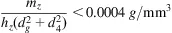
Weights and key dimensions, such as the maximum diameter of the valve head dg, diameter of valve stem dt, and total height hz for valves on the market that are made of steel and TiAl alloys and used in the same engines were measured. The results allow for the assumption of an approximate criterion for classifying valves as lightweight, involving the fulfillment of the following condition [5]:
Chapter 2
Principles of valve train operation
Abstract
In the chapter it was explained, that the valve performance depends on the engine type: spark-ignition and compression ignition, the type and a method for delivering components needed to carry out the combustion process in the engine, especially the fuel and oxidizer. It was also mentioned engines that use variable cycles and the engines of a homogeneous charge compression ignition (HCCI). In the chapter the departure from the basic engine valve timing was described. It was also explained concepts of lead, lag and overlap. It was presented valve timing diagrams for four–stoke and two–stroke engines both of the SI and CI type. It was explained the concept of the scavenging. It was also described the rotary port system for IC engines, poppet valves’ arrangement, types of valve train systems with poppet valves. It was discussed the classification of Variable Valve Actuation Technology, the role of Variable Valve Timing, and the deactivation of cylinder and valve.
Keywords
engine types; lead; lag; overlap; scavenging; rotary port system; poppet valves arrangement; variable valve actuation; variable valve timing; cylinder deactivation; valve deactivation
The operation of valve train elements occurs under conditions of the repetitive operating cycle of the engine and depends on its course and parameters. Therefore, the engine type is one of the principal determinants of valve performance. Most cases of valve trains are seen in four-stroke cycle engines, and only a small portion of cases concern two-stroke engines.
There are two main engine types: spark ignition (SI), operating in a version of the Otto cycle, and compression ignition (CI), which operates in a version of the diesel cycle.
The valve performance is also determined by the type and the method of delivery of the components necessary to carry out the combustion process in the engine, especially fuel and the oxidizer. Both of these and interactions between them have an effect on pressure, temperature, the course of the combustion, and the produced atmosphere in which the valves operate. In SI engines, petrol is the common fuel; however, these engines may be powered with other fuels, such as autogas (LPG), methanol, ethanol, bioethanol, compressed natural gas, hydrogen, and nitromethane [6]. In most cases, CI engines are fuelled with gas oil.
There are also engines that use variable cycles. An example is the Ricardo engine [7], in which the low-speed range of the two-stroke cycle is used and the four-stroke cycle is used at higher speeds. This involves the need to ensure greater efficiency throughout the engine speed range. This engine enables fuel savings of 27%.
Relatively recently, engines with a homogeneous charge compression ignition (HCCI) have been developed that are hybrids of SI engines based on CI engine processes. The HCCI engine combines the high performance of the CI engine with the low NOx and particulate matter emissions of the SI engine. In the HCCI engine, fuel and air are mixed before combustion, as in the SI engine, and compression of the mixture causes self-ignition in the same way as in the CI engine. There are various methods of HCCI ignition control: inlet air temperature control [8], variable compression ratio [9], dual fuel injection [10], variable valve timing [11], and exhaust gas recirculation [12].
Withdrawal from the Basic Valve...
Table of contents
- Cover image
- Title page
- Table of Contents
- Copyright
- Preface
- Chapter 1. Introduction
- Chapter 2. Principles of valve train operation
- Chapter 3. Spark-ignition engine valve trains
- Chapter 4. Compression-ignition engine valve trains
- Chapter 5. Valve train thermodynamic effects
- Chapter 6. Valve train kinetic effects
- Chapter 7. Valve train tribology
- Chapter 8. Mechanical component design and analysis
- Chapter 9. Advanced mechanical valve train design and analysis
- Chapter 10. Future valve train systems
- Chapter 11. Research on valve trains
- References
- Index
Frequently asked questions
Yes, you can cancel anytime from the Subscription tab in your account settings on the Perlego website. Your subscription will stay active until the end of your current billing period. Learn how to cancel your subscription
No, books cannot be downloaded as external files, such as PDFs, for use outside of Perlego. However, you can download books within the Perlego app for offline reading on mobile or tablet. Learn how to download books offline
Perlego offers two plans: Essential and Complete
- Essential is ideal for learners and professionals who enjoy exploring a wide range of subjects. Access the Essential Library with 800,000+ trusted titles and best-sellers across business, personal growth, and the humanities. Includes unlimited reading time and Standard Read Aloud voice.
- Complete: Perfect for advanced learners and researchers needing full, unrestricted access. Unlock 1.5M+ books across hundreds of subjects, including academic and specialized titles. The Complete Plan also includes advanced features like Premium Read Aloud and Research Assistant.
We are an online textbook subscription service, where you can get access to an entire online library for less than the price of a single book per month. With over 1.5 million books across 990+ topics, we’ve got you covered! Learn about our mission
Look out for the read-aloud symbol on your next book to see if you can listen to it. The read-aloud tool reads text aloud for you, highlighting the text as it is being read. You can pause it, speed it up and slow it down. Learn more about Read Aloud
Yes! You can use the Perlego app on both iOS and Android devices to read anytime, anywhere — even offline. Perfect for commutes or when you’re on the go.
Please note we cannot support devices running on iOS 13 and Android 7 or earlier. Learn more about using the app
Please note we cannot support devices running on iOS 13 and Android 7 or earlier. Learn more about using the app
Yes, you can access Tribological Processes in the Valve Train Systems with Lightweight Valves by Krzysztof Jan Siczek in PDF and/or ePUB format, as well as other popular books in Technology & Engineering & Automotive Transportation & Engineering. We have over 1.5 million books available in our catalogue for you to explore.