eBook - ePub
Buckling and Ultimate Strength of Ship and Ship-like Floating Structures
- 536 pages
- English
- ePUB (mobile friendly)
- Available on iOS & Android
eBook - ePub
Buckling and Ultimate Strength of Ship and Ship-like Floating Structures
About this book
Buckling and Ultimate Strength of Ship and Ship-like Floating Structures provides an integrated state-of-the-art evaluation of ship structure mechanics including buckling, plastic failure, ultimate strength, and ultimate bending moments. For the design of any industrial product, it is necessary to understand the fundamentals in the failure behavior of structures under extreme loads. Significant developments have been made in understanding the analysis method of plastic collapse and behavior and strength of structures accompanied by buckling.
Written by two of the foremost experts in international ship design and ocean engineering, this book introduces fundamental theories and methods as well as new content on the behavior of buckling/plastic collapse that help explain analysis like the initial imperfections produced by welding and the ultimate strength of plates, double bottom structures of bulk carriers, and ship and FPSO hull girders in longitudinal bending.
Rounding out with additional coverage on floating structures such as oil and gas platforms and LNG/FLNG structural characteristics, Buckling and Ultimate Strength of Ship and Ship-like Floating Structures is a must-have resource for naval architects and other marine engineering professionals seeking to gain an in-depth understanding of the technological developments in this area.
- Explains how the initial imperfections produced by welding, residual stress, and initial deflection in panels influence the collapse behavior and the compressive ultimate strength of rectangular plates
- Evaluates the ultimate strength of plate girders under bending and shearing as well as combined bend/shear loads
- Provides fundamental theories, simple formulas, and analytical methods such as Finite Element Method or Smith's Method to simulate and evaluate buckling/plastic collapse behavior and strength of plates under various conditions
- Authored by two of the foremost experts in international ship design and ocean engineering
- Includes additional coverage on floating structures such as oil and gas platforms
Trusted by 375,005 students
Access to over 1.5 million titles for a fair monthly price.
Study more efficiently using our study tools.
Information
Chapter 1
Introduction
Abstract
This chapter is divided into three parts: (1) what is buckling/plastic collapse of members and systems in ship and ship-like floating structures; (2) a short historical review of the research works related to the subject of this textbook; and (3) the concrete contents of this textbook.
In the first part, the structure of ship and ship-like floating structures is briefly explained, together with the working loads and resulting deformations. Then, taking a column, a plate, and a stiffened plate as an example, fundamental buckling/plastic collapse behavior is explained.
In the second part, some important issues are introduced that were important in the development of today’s technology including the finite element method.
In the last part, the contents of the nine chapters and three appendices of this textbook are briefly introduced.
Keywords
Introduction; Buckling strength; Ultimate strength; Ship and ship-like floating structures; Short historical review; Deformation; External loads; Contents
1.1 Buckling/Plastic Collapse of Ship and Ship-Like Floating Structures
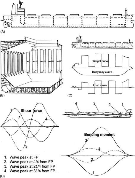
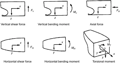
A hull of ship and ship-like floating structures is a box girder structure composed of plates and stiffeners as indicated in Fig. 1.1A and B. The main loads acting on a hull girder are distributed lateral loads such as hull weight and cargo weight as well as buoyancy force and wave force; see Fig. 1.1C and D. Inertia forces also act on a navigating ship in waves. Such distributed loads produce bending moment, torsional moment, and shear force as well as axial force in the cross-section, which are shown in Fig. 1.2.
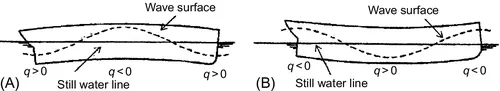
The distributed loads in the vertical direction may produce bending deformation in a hull girder, as illustrated in Fig. 1.3. Under sagging conditions, the deck plate is subjected to thrust (or in-plane compression) and the bottom plate to tension. Due to this in-plane compression, the deck plate may undergo buckling when extreme bending moment acts. On the other hand, in hogging, the deck plate is in tension and the bottom plate in thrust, and the bottom plate may undergo buckling.
Here, buckling is a phenomenon that a structural member such as a plate, a stiffened plate, a stiffener, a column, etc., which are under thrust load deflect in an out-of-plane direction when the load reaches to a certain critical value. After the buckling, deflection begins to increase in addition to the in-plane (or axial) displacement, which causes a reduction in the in-plane (or axial) stiffness. This is because a deflected structural member shows less resistance against in-plane (or axial) compressive force compared to a flat (or straight) structural member.
One of the structural problems caused by buckling is the reduction in in-plane stiffness mentioned above. Another problem is the earlier occurrence of yielding. This is because bending stress is produced by deflection in addition to in-plane (or axial) stress. The occurrence of yielding further reduces the stiffness.
When a certain structural member undergoes buckling, its load-carrying capacity decreases. This causes redistribution of internal forces in unbuckled structural members and increases the internal forces in these structural members, which may lead to the progressive occurrence of buckling failure of these structural members. If the load increases further, progressive buckling may results in the collapse of a whole structure. This was the reason why occurrence of buckling was not allowed in any members in ship structures in old classification societies’ rules.
In a strict sense, buckling is a bifurcation phenomenon that stable deformation changes from in-plane (or axial) deformation to in-plane (or axial) plus out-of-plane deformations. Therefore, to have buckling in a strict sense, the structural member has to be completely flat (or straight) before it is loaded; that is, it has to be completely free from initial distortion/deflection.
However, a ship structure is constructed connecting members by welding, and the structural members are accompanied by initial imperfections such as initial distortion/deflection and welding residual stress. This implies that buckling in a strict sense does not occur in actual structures, since they are accompanied by initial distortion or initial deflection.
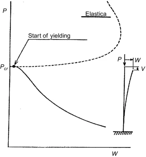
Here, a straight column member subjected to axial thrust is considered. In this case, deflection increases with no increase in the applied axial load for a while beyond buckling. However, the capacity again starts to increase and a column can sustain further load if its behavior is perfectly elastic. This is called Elastica [1]; see Fig. 1.4. On the other hand, an actual column member undergoes yielding by bending after buckling has occurred, and soon its capacity starts to decrease with an increase in the deflection. In this sense, buckling strength of a column member is the maximum load-carrying capacity and can be regarded as the ultimate strength. Therefore, the occurrence of buckling should not be allowed in column members.
In the case of a simply supported plate subjected to uniaxial thrust, buckling/plastic collapse behavior is indicated in Fig. 1.5A and B in terms of average stress-central deflection and average stress-average strain relationships, respectively. Behavior of both thin and thick plates is indicated. In the case of a thin plate, lateral deflection starts to develop beyond the buckling point, A, when a plate is flat. When a plate is accompanied by small initial deflection, lateral deflection gradually increases from the beginning of loading, although the increasing rate is low. Above the buckling load, deflection starts to increase rapidly as in the case of no initial deflection. Such a phenomenon is also called buckling in a broad sense.
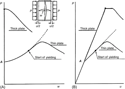
Beyond the buckling, capacity further increases with the increase in buckling deflection, but in-plane stiffness (slope of average stress-average strain curve) decreases to around 0.4 through 0.5 times the Young’s modulus, depending on the aspect ratio of the plate. For a while, the in-plane stiffness is almost constant, but again starts to decrease gradually after yielding has started. Finally, the stiffness becomes zero and the ultimate strength is attained. Then, the capacity starts to decrease beyond the ultimate strength.
In the case of a thick plate, yielding starts to take place before the plate undergoes buckling. In this case, the maximum load-carrying capacity—that is the ultimate strength—is nearly equal to the fully plastic strength, and this capacity is kept until buckling takes place if the material does not show remarkable strain hardening. After the buckling has occurred, capacity starts to decrease with the increase in the buckling deflection.
Welding residual stress also affects the buckling strength as well as the ultimate strength. If compressive residual stress exists at the location where buckling deflection develops, buckling strength is reduced by welding residual stress. On the contrary, welding residual stress increases the buckling strength if tensile residual stress exists in the region where buckling deflection develops.
Buckling/plastic collapse behavior of a stiffened plate is then considered, which is a fundamental structural unit composing a ship’s hull girder. This is schematically shown in Fig. 1.6. This is the case of a stiffened plate subjected to thrust (or in-plane compression) in the direction of stiffeners. In actual structure, size of stiffeners are so determined that local panels partitioned by stiffeners buckle before overall buckling of a whole stiffened plate takes place. The figure indicates representative average stress-average strain relationships for such stiffened plates.
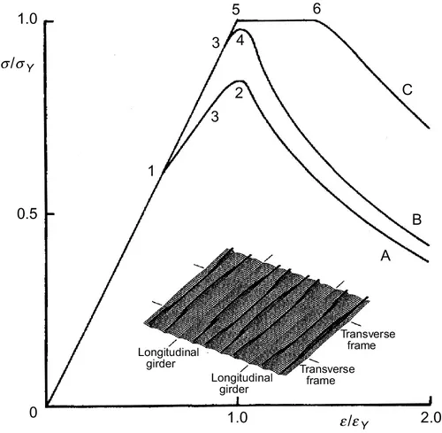
When the slenderness ratio of the local panel is high—that is when the local panel is thin—the average stress-average strain relationship follows Curve A. In this case, elastic panel buckling takes place locally at Point 1, and the stiffness decreases hereafter because large deflection in the local panel rapidly develops. At Point 3, yielding starts to take place, and at Point 2, the overall buckling occurs as a stiffened panel. Point 2 stands for the ultimate strength.
When the slenderness ratio of the panel is lower, the average stress-average strain relationship is represented by Curve B. In this case, initial yielding takes place at Point 3, and the ultimate strength is attained at Point 4 by overall buckling as a stiffened plate.
When the panel and the stiffener have a much lower slenderness ratio, the average stress-average strain relationship follows Curve C. In this case, yielding starts at Point 5, and soon the general yielding takes place all over the stiffened plates. However, no deflection is produced at this moment. At Point 6, either the panel or the stiffener undergoes buckling, and the capacity decreases hereafter with the increase in deflection in the panel or in the stiffener. After this, plastic deformation concentrates along one line perpendicular to the loading direction and elastic unloading occurs in the rest of the stiffened plate.
In general, ship structures are designed so that b...
Table of contents
- Cover image
- Title page
- Table of Contents
- Copyright
- Preface
- Acknowledgments
- Chapter 1: Introduction
- Chapter 2: Initial Imperfections due to Welding
- Chapter 3: Fundamental Theory and Methods of Analysis to Simulate Buckling/Plastic Collapse Behavior
- Chapter 4: Buckling/Plastic Collapse Behavior and Strength of Rectangular Plate Subjected to Uni-Axial Thrust
- Chapter 5: Buckling/Plastic Collapse Behavior and Strength of Rectangular Plates Subjected to Combined Loads
- Chapter 6: Buckling/Plastic Collapse Behavior and Strength of Stiffened Plates
- Chapter 7: Buckling/Plastic Collapse Behavior and Strength of Plate Girders Subjected to Combined Bending and Shear Loads
- Chapter 8: Progressive Collapse Behavior and Ultimate Strength of Hull Girder of Ship and Ship-Like Floating Structures in Longitudinal Bending
- Chapter 9: Theoretical Background and Assessment of Existing Design Formulas to Evaluate Ultimate Strength
- Chapter 10: Buckling/Plastic Collapse Behavior of Structural Members and Systems in Ship and Ship-Like Floating Structures
- Appendix A: Chronological Table of Study on Buckling/Ultimate Strength
- Appendix B: Fundamentals in Idealized Structural Unit Method (ISUM)
- Appendix C: Structural Characteristics of Representative Ship and Ship-Like Floating Structures
- Index
Frequently asked questions
Yes, you can cancel anytime from the Subscription tab in your account settings on the Perlego website. Your subscription will stay active until the end of your current billing period. Learn how to cancel your subscription
No, books cannot be downloaded as external files, such as PDFs, for use outside of Perlego. However, you can download books within the Perlego app for offline reading on mobile or tablet. Learn how to download books offline
Perlego offers two plans: Essential and Complete
- Essential is ideal for learners and professionals who enjoy exploring a wide range of subjects. Access the Essential Library with 800,000+ trusted titles and best-sellers across business, personal growth, and the humanities. Includes unlimited reading time and Standard Read Aloud voice.
- Complete: Perfect for advanced learners and researchers needing full, unrestricted access. Unlock 1.5M+ books across hundreds of subjects, including academic and specialized titles. The Complete Plan also includes advanced features like Premium Read Aloud and Research Assistant.
We are an online textbook subscription service, where you can get access to an entire online library for less than the price of a single book per month. With over 1.5 million books across 990+ topics, we’ve got you covered! Learn about our mission
Look out for the read-aloud symbol on your next book to see if you can listen to it. The read-aloud tool reads text aloud for you, highlighting the text as it is being read. You can pause it, speed it up and slow it down. Learn more about Read Aloud
Yes! You can use the Perlego app on both iOS and Android devices to read anytime, anywhere — even offline. Perfect for commutes or when you’re on the go.
Please note we cannot support devices running on iOS 13 and Android 7 or earlier. Learn more about using the app
Please note we cannot support devices running on iOS 13 and Android 7 or earlier. Learn more about using the app
Yes, you can access Buckling and Ultimate Strength of Ship and Ship-like Floating Structures by Tetsuya Yao,Masahiko Fujikubo in PDF and/or ePUB format, as well as other popular books in Technology & Engineering & Mechanical Engineering. We have over 1.5 million books available in our catalogue for you to explore.