eBook - ePub
The Grouting Handbook
A Step-by-Step Guide for Foundation Design and Machinery Installation
- 222 pages
- English
- ePUB (mobile friendly)
- Available on iOS & Android
eBook - ePub
The Grouting Handbook
A Step-by-Step Guide for Foundation Design and Machinery Installation
About this book
Minimize loss of revenue and the downtime of critical assets by avoiding foundation cracking, poor bonds, and initial alignment changes. After their successful introduction as a maintenance material, machinery grouts are now being used for equipment placement in new construction. While certainly suitable for both markets and applications, a successful installation depends on proper grout selection, application, foundation preparation, and forming methods. Therefore, guidelines on their uses and limitations are needed for engineers and maintenance personnel.
Based on 45 years of field experience, The Grouting Handbook collects a vast amount of information into a practical and user-friendly reference for mechanical and civil engineers. The book focuses on four basic elements of grouting:
- The soil and its load-carrying capability;
- The foundation and its mass, design, concrete mix, installation and curing procedures;
- Anchor bolt technology, design and installation;
- Epoxy grout comparison, material selection and installation.
From the ground up, The Grouting Handbook takes you step by step through the grouting process. Clear, straightforward directions give you details on preparing the foundation and surface and selecting the best material and method. Comprehensive yet concise, this is a convenient handbook for veteran and rookie engineers alike.
- Organizes a comprehensive amount of information into an easy-to-use reference
- Provides advice for selecting the proper grouting material and method for the task at hand
- Contains tips and practical solutions for common problems
Trusted by 375,005 students
Access to over 1.5 million titles for a fair monthly price.
Study more efficiently using our study tools.
Information
1
The Foundation
Your Machinery reliability will be directly proportional to your investment in a properly designed and installed foundation. Shortcuts or poor practices taken here will directly affect rotating equipment life.
The Initial Machinery Foundation Design
We spend a lot of engineering time and money designing a foundation for a piece of equipment. Contrary to popular belief, machinery foundation structural design is still evolving. We must rethink today’s foundations to eliminate the design stress concentration points to reduce the possibility of a crack developing in the concrete. The most common causes of cracking in large concrete foundations are inside right angles (Figure 1.1) built into the foundations. You can easily eliminate these stresses by incorporating a chamfer of 3–6 in. into the design.
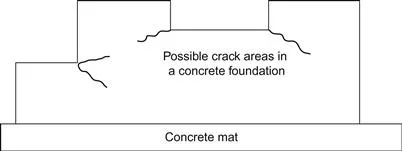
Figure 1.1 Depending on the dynamics of the machinery installed, this type of cracking can be caused by the right angle stress concentration points originally designed into the foundation, and by the thermal growth of the machine.
Reciprocating Compressor and Engine Foundations
Machinery foundation structural design is still evolving. Even today, we do not give enough thought or research to designing a foundation for the long term. The foundation block width should be greater than its height to overcome the cantilever effect experienced by most reciprocating engines or compressors. A good rule of thumb for engine and compressor foundation design is to keep the blocks low and wide (Figure 1.2). The center of gravity of the foundation’s total mass (block and mat) should be within 6–8 in. of the vertical centerline of the crankshaft.
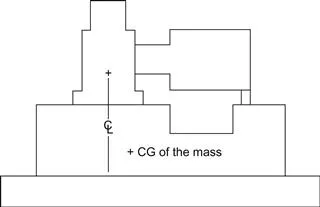
Figure 1.2 For reciprocating engines and compressors, the centerline of the crankshaft should be within 6–8 in. of the center of gravity of the total foundation mass.
Another rule of thumb calls for the mass of a machinery foundation for a reciprocating compressor and driver to be, at minimum, five times the combined weight of those items. In some cases, mass ratios may go as high as eight times the machine weight. This ratio depends on the unbalanced forces generated by the machine.
Most original equipment manufacturers (OEMs) typically will supply a drawing that specifies a generic foundation design for their machine. This drawing usually has a disclaimer saying something like:
The XYZ Company offers this design only to show locations of foundation bolts and general dimension recommendations where soil conditions are satisfactory. XYZ assumes no liability whatsoever for the foundation design. Proper concrete mixture, correct reinforcement, sufficient mass, and satisfactory footing is essential to give permanent support and prevent vibrations. If local soil conditions are poor, a competent foundation engineer should be employed.
Skid-Mounted Equipment Foundations
As mentioned earlier, the general rule of thumb for reciprocating equipment foundation design is for the foundation to be a minimum of five times the mass of the operating equipment. For example, if a reciprocating engine and high-speed compressor assembly weighed 25,000 lbs, the underlying concrete mass should weigh about 125,000 lbs. Sometimes, installing a foundation of this mass for a reciprocating skid-mounted assembly is not practical or even feasible. To compensate for this lack of foundation mass, you sometimes can fill the individual skid compartments with concrete at the time of fabrication. The idea is for this concrete to act as a damping agent by adding mass to the skid. The concrete is added after the skid has been fabricated and painted. Unless some type of reinforcing steel is welded to the inside of the individual skid compartments, the concrete will not perform as expected because it will not bond to the painted steel. If this occurs, its damping characteristics are reduced.
In general, the foundation mass for skid-mounted equipment installations of this type need to be a minimum of 1½ times the weight of the total completed skid package (Figure 1.3).
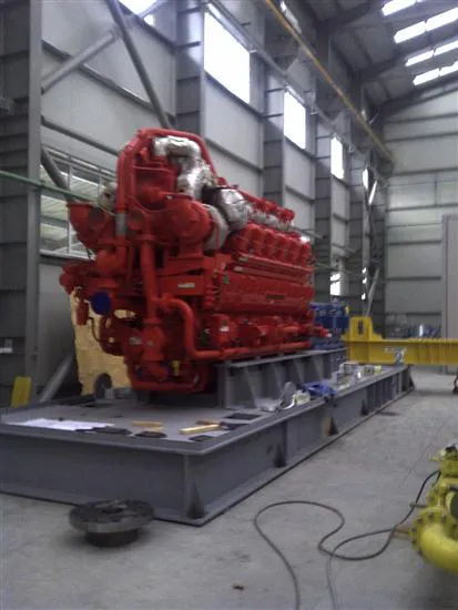
Figure 1.3 Skid-mounted compressor unit.
On some skid-mounted equipment, the natural frequency of the skids has been measured at 200 Hz or more. The natural frequency of the skid is totally dependent on the skid design and the equipment operating frequency.
Foundations for Centrifugal Pumps
Over the years, several papers and articles have been written on epoxy grouting of American Petroleum Institute (API) and American National Standards Institute (ANSI) pumps. The generally accepted rule for pump foundations is that they should be three times the mass of the pump, driver, and steel baseplate. Other than that, not much has been written about the basic foundation dimensions for API and ANSI pumps.
Many years ago, Ray Dodd of Chevron’s Pascagoula, Mississippi facility developed a rule of thumb concerning the sizing of pump foundations (Figure 1.4). He found a way to determine if pump foundation size is adequate. If the lines pass through the bottom of the foundation, the foundation is adequate. If the lines pass through the sides, then the foundation is too narrow.
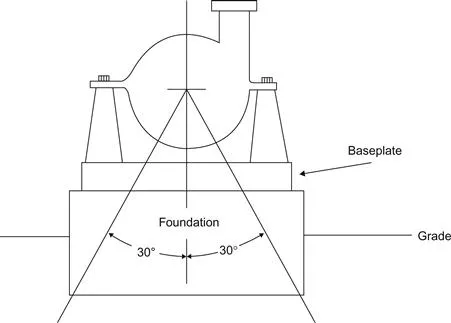
Figure 1.4 Lines drawn 30° down from the shaft centerline are a good rule of thumb to show if pump foundation is wide enough.
He arrived at this rule of thumb from a blend of engineering principles and his experience in the field of rotating equipment. His intent was to provide a fast yet simple method for the evaluation of existing or future pump foundations, something that could also be used to supplement sketchy general installation data from the pump OEM. Additionally, Ray found that this rule of thumb was also an excellent way to verify foundation designs furnished by the pump manufacturers.
Today’s pumps differ in their design and construction but retain the same basic dynamic principles that apply to all of them. You must consider both the dynamic and static forces of the pump and its foundation for adequate long-term soil support. According to Ray Dodd’s rule of thumb, a well designed pump foundation and steel pump base allows imaginary lines extending downward at 30°, from either side of the vertical through the pump shaft, to pass through the bottom of the foundation and not the sides.
The following guidelines will apply to good foundation design for pumps:
• The mass of the concrete foundation should be a minimum of three times the mass of the supported equipment and should have sufficient rigidity to withstand the axial, transverse, and torsional loadings generated by these machines.
• The foundation should be 6 in. wider than the baseplate for pumps up to 500 hp and 10 in. wider for larger machines.
• The concrete used in the foundation should have a minimum tensile strength of 350 psi.
• Epoxy grout should always be used to mate the pump baseplate to the foundation.
These guidelines and Ray Dodd’s rule of thumb can be used as a quick evaluation of a suspected pump foundation as potential sources of vibration.
Most pump foundation vibrations are usually observed at rotational speed. If you identify a foundation as the source of a vibration problem, it may be due to inadequate mass or configuration. Adding concrete mass to an existing foundation may not be the answer. If you add a concrete mass equal to the full weight of the pump and its steel baseplate to the existing foundation of a machine, the resulting velocity energy will be approximately half that of the original design, providing that the cold joint can be eliminated by using an epoxy bonding agent or by later pressure-injecting the cold joint with epoxy.
Adding twice the mass of the pump and baseplate to an existing foundation reduces the vibration energy to about 1⁄3 of the amount experienced on the original foundation design without the added mass.
W.E. Nelson, P.E., was a turbo machinery consultant in Dickinson, TX. I worked with him in one of the largest refineries in the world, and he was my mentor. He said that “his experience with adding additional concrete mass to an existing pump’s foundations was less than satisfactory.” He found that, of the numerous existing pump foundations that received this additional mass of concrete, only 20% performed as expected. The remaining 80% showed no appreciable improvement in the reduction of vibration. Additionally, he found that for the same cost as the additional concrete for mass, associated rebar, and doweling, he could have replaced the existing foundation with a correctly sized one.
Perry Monroe, P.E. (retired turbo machinery consultant in Livingston, TX), cautions tha...
Table of contents
- Cover image
- Title page
- Table of Contents
- Copyright
- Dedication
- Preface
- About the Author
- Acknowledgments
- 1. The Foundation
- 2. Anchor Bolts
- 3. Cement Grouts
- 4. Epoxy Grout
- 5. Selecting an Epoxy Grout
- 6. The Use of Rebar and Expansion Joints in Epoxy Grout
- 7. Cracking in Epoxy Grout
- 8. Making Deep Pours with Epoxy Grout
- 9. Surface Preparation of Concrete and Steel
- 10. Pressure Grouting
- 11. Pump Grouting
- 12. Skid Grouting
- 13. Chocking
- 14. Grouting Specifications
- 15. Drawings Only
- References
Frequently asked questions
Yes, you can cancel anytime from the Subscription tab in your account settings on the Perlego website. Your subscription will stay active until the end of your current billing period. Learn how to cancel your subscription
No, books cannot be downloaded as external files, such as PDFs, for use outside of Perlego. However, you can download books within the Perlego app for offline reading on mobile or tablet. Learn how to download books offline
Perlego offers two plans: Essential and Complete
- Essential is ideal for learners and professionals who enjoy exploring a wide range of subjects. Access the Essential Library with 800,000+ trusted titles and best-sellers across business, personal growth, and the humanities. Includes unlimited reading time and Standard Read Aloud voice.
- Complete: Perfect for advanced learners and researchers needing full, unrestricted access. Unlock 1.5M+ books across hundreds of subjects, including academic and specialized titles. The Complete Plan also includes advanced features like Premium Read Aloud and Research Assistant.
We are an online textbook subscription service, where you can get access to an entire online library for less than the price of a single book per month. With over 1.5 million books across 990+ topics, we’ve got you covered! Learn about our mission
Look out for the read-aloud symbol on your next book to see if you can listen to it. The read-aloud tool reads text aloud for you, highlighting the text as it is being read. You can pause it, speed it up and slow it down. Learn more about Read Aloud
Yes! You can use the Perlego app on both iOS and Android devices to read anytime, anywhere — even offline. Perfect for commutes or when you’re on the go.
Please note we cannot support devices running on iOS 13 and Android 7 or earlier. Learn more about using the app
Please note we cannot support devices running on iOS 13 and Android 7 or earlier. Learn more about using the app
Yes, you can access The Grouting Handbook by Donald M. Harrison in PDF and/or ePUB format, as well as other popular books in Technology & Engineering & Agronomy. We have over 1.5 million books available in our catalogue for you to explore.