- 334 pages
- English
- ePUB (mobile friendly)
- Available on iOS & Android
eBook - ePub
Well Productivity Handbook
About this book
With rapid changes in field development methods being created over the past few decades, there is a growing need for more information regarding energizing well production. Written by the world's most respected petroleum engineering authors, Well Productivity Handbook provides knowledge for modeling oil and gas wells with simple and complex trajectories. Covering critical topics, such as petroleum fluid properties, reservoir deliverability, wellbore flow performance and productivity of intelligent well systems, this handbook explains real-world applications illustrated with example problems.
Tools to learn more effectively

Saving Books

Keyword Search

Annotating Text

Listen to it instead
Information
Topic
Physical SciencesSubtopic
Geology & Earth SciencesChapter 1
Introduction
1.1 Wells and Reservoirs
Oil and gas wells are used for extracting crude oil and natural gas from oil and gas reservoirs. There are three types of wells: oil, gas condensate, and gas. Their classification depends on the producing gas-oil ratio (GOR). Gas wells produce at a GOR greater than 100,000 scf/stb; condensate wells produce at a GOR less than 100,000 scf/stb but greater than 5,000 scf/stb; and oil wells produce at a GOR less than 5,000 scf/stb. Unit conversion factors for the SI systems are provided in Appendix A.
A naturally flowing well consists of a reservoir segment, wellbore, and wellhead (Figure 1-1).
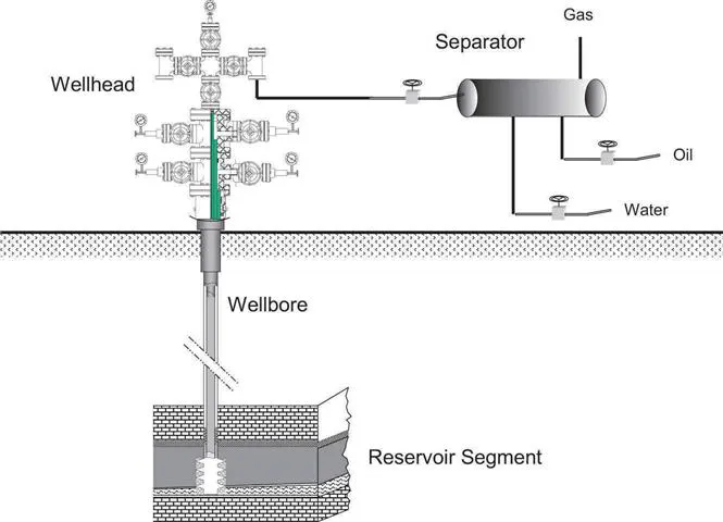
The reservoir segment supplies the wellbore with production fluids (crude oil and/or natural gas). The wellbore provides a path for the fluids to flow from bottom hole to the surface. The wellhead permits control of the fluid production rate.
An oil or gas reservoir is a single porous and permeable underground rock formation containing an individual bank of fluid hydrocarbons, and confined by impermeable rock or water barriers. It contains a single natural pressure system. An oil or gas field is an underground region consisting of one or more reservoirs, all related to the same structural feature. An oil or gas pool is a more extensive region containing one or more reservoirs, in isolated structures.
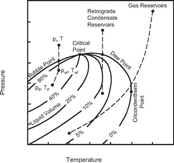
Engineers classify oil, gas condensate, and gas reservoirs on the basis of the initial reservoir condition and hydrocarbon composition. An oil that is at a pressure above its bubble point is called an undersaturated oil, because it can hold more dissolved gas at any given temperature (Figure 1-2). An oil that is at its bubble-point pressure is called a saturated oil because it can dissolve no more gas at any given temperature. In an undersaturated oil reservoir, single (liquid) phase flow occurs. Two-phase (liquid oil and free gas) flow occurs in a saturated oil reservoir.
Oil reservoirs are further classified on the basis of boundary type, which determines the driving mechanism. The three types of reservoirs are
• Water-drive
• Gas-cap drive
• Dissolved-gas drive
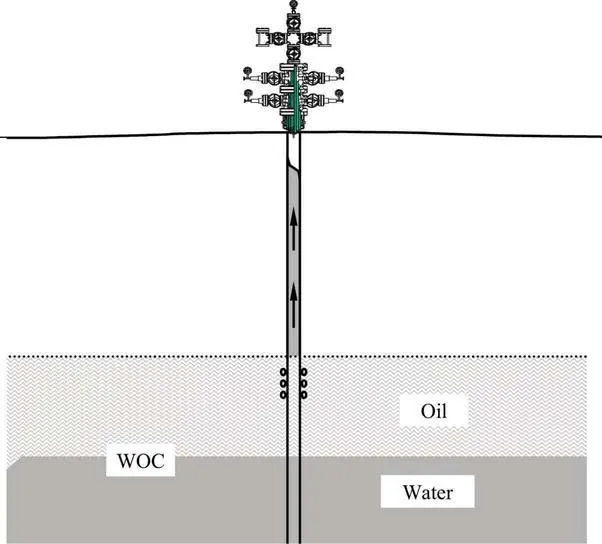
In water-drive reservoirs, the oil zone is connected through a continuous pressure path to a ground water system (aquifer). The pressure due to the water column forces the oil and gas to the top of the reservoir against the impermeable barrier that restricts further migration (the trap boundary). This pressure forces the oil and gas toward the wellbore. Under a constant oil production rate, an active water-drive reservoir will maintain reservoir pressure longer, compared to other driving mechanisms. Edge-water drive reservoirs are better producers than bottom-water drive reservoirs. The reservoir pressure remains at its initial value above bubble-point pressure for longer, maintaining single-phase liquid flow in the reservoir for maximum productivity. An edge-water drive reservoir can also maintain steady-state flow condition for a significantly longer time before water breakthrough into the well. Bottom-water drive reservoirs are more troublesome because of water-coning problems that affect oil production economics due to water treatment and disposal issues (Figure 1-3).
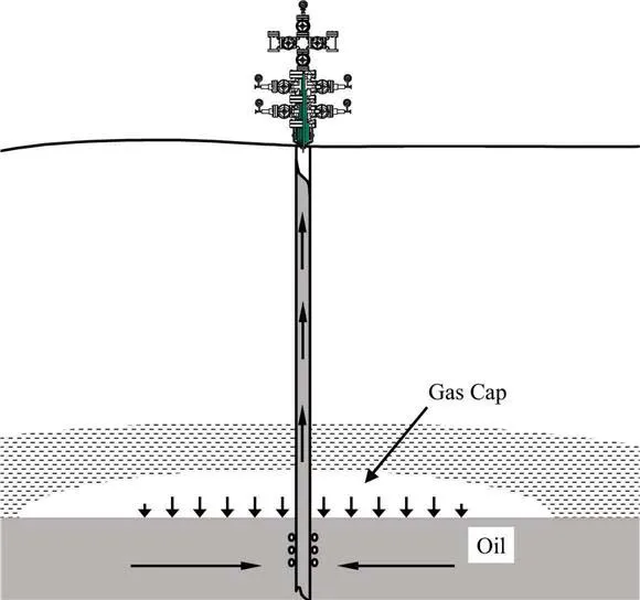
In gas-cap drive reservoirs, the gas in the gas cap expands and compensates for pressure depletion in the oil zone due to production (Figure 1-4). Thus, the oil below the gas cap will produce naturally, longer. If the gas in the gas cap is extracted early in field development, the reservoir pressure will decrease rapidly. Some oil reservoirs display both water and gas-cap driving mechanisms.
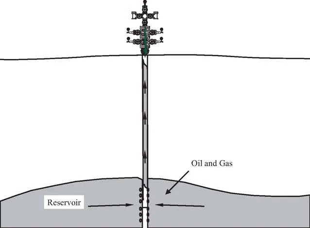
A dissolved-gas drive reservoir is also called a solution-gas drive reservoir (Figure 1-5). The oil reservoir has a fixed volume, bounded by impermeable structures or layers (faults or pinch-outs). In dissolved-gas drive oil reservoirs, the driving mechanism is gas held in solution in the oil (and water, if any). During production, the dissolved gas expands and partially compensates for the inevitable pressure decline in reservoir production. Dissolved-gas drive is a weaker mechanism in a volumetric reservoir than either water-drive or gas-drive. If the reservoir pressure drops to a value below the bubble-point pressure of the oil, gas escapes from the oil, and oil-gas two-phase competing flow begins. This reduces the effective permeability of the reservoir to the oil, increases the viscosity of the remaining oil, and thus reduces well productivity and ultimate oil recovery. Early attention to pressure maintenance can increase ultimate oil recovery in the solution-gas drive reservoir.
For a typical oil well that delivers fluids to the surface solely due to the natural pressure of the reservoir, a completed wellbore is composed of casings, tubing, packers, and optional down-hole chokes (Figure 1-6).
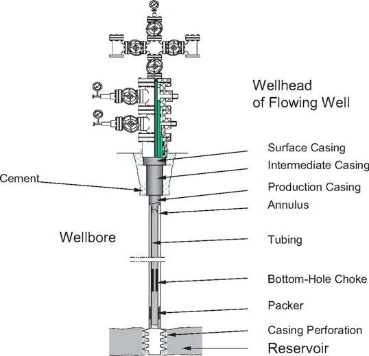
A wellbore is like an upside-down telescope. The large diameter borehole section is at the top of the well. Each successive section of the wellbore is cased to the surface using narrower and narrower strings of nested casing. Lastly, a liner is inserted down the well that laps over the last casing at its upper end. Each casing or liner is cemented into the well (usually up to at least where the cement overlaps the previous cement job).
The final casing in the well is the production casing (or production liner). Once this casing has been cemented, production tubing is run down the well. A packer is usually used near the bottom of the tubing to isolate the annulus between tubing and casing, and to guide the produced fluids into the tubing. Packers can be actuated mechanically or hydraulically. The production tubing is often provided with a bottom-hole choke (particularly during initial well flow) to control the well flow and restrict overproduction.
Tubing strings are installed in most production wells. A tubing string provides a good seal and allows gas expansion to help lift the oil to the wellhead. The American Petroleum Institute (API) defines tubing size using nominal diameter and weight-per-foot. The nominal diameter refers to the inside diameter (I.D.) of the tubing. The tubing outside diameter (O.D.) determines the tubing’s weight-per-foot. Steel grade used in tubing is designated H-40, J-55, C-75, L-80, N-80, C-90, and P-105, where the numbers represent minimum yield strength in units of 1,000 psi. The minimum performance properties of production tubing are given in Appendix B.
The wellhead is the surface equipment set below the master valve and includes multiple casing heads and a tubing head. A casing head is a mechanical assembly used for hanging a casing string. The lowermost casing head is threaded, flanged, or studded into the surface casing (Figure 1-7). Depending on the casing programs used during drilling, several casing heads might be installed. The casing head has a bowl which supports the casing hanger, which is threaded into the top of the production casing (or utilizes friction grips to hold the casing). As in the case of the production tubing, the production casing is suspended in tension so that the casing hanger actually supports it down to the freeze point. In a similar manner, the intermediate casings are supported by their respective casing hangers and bowls. The casing heads are all supported by the surface casing, which is in compression and cemented to the surface. A well completed with three casing strings will have two casing heads. The uppermost casing head supports the production casing, while the lowermost casing head is attached to and is supported by the surface casing.
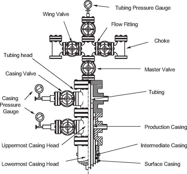
Table of contents
- Cover image
- Title page
- Table of Contents
- Copyright
- Dedication
- Preface
- List of Symbols
- List of Figures
- List of Tables
- Chapter 1. Introduction
- Chapter 2. Properties of Petroleum Fluids
- Chapter 3. Properties of Petroleum Reservoirs
- Chapter 4. Reservoir Deliverability
- Chapter 5. Wellbore Performance
- Chapter 6. Productivity of Wells with Simple Trajectories
- Chapter 7. Productivity of Wells with Complex Trajectories
- Chapter 8. Productivity of Intelligent Well Systems
- Appendix A. Unit Conversion Factors
- Appendix B. Minimum Performance Properties of API Tubing
- Appendix C. Mathematical Model for Obtaining Oil Rate Correction Factor Fo
- Appendix D. Mathematical Model for Obtaining Gas Rate Correction Factor Fg
- Index
Frequently asked questions
Yes, you can cancel anytime from the Subscription tab in your account settings on the Perlego website. Your subscription will stay active until the end of your current billing period. Learn how to cancel your subscription
No, books cannot be downloaded as external files, such as PDFs, for use outside of Perlego. However, you can download books within the Perlego app for offline reading on mobile or tablet. Learn how to download books offline
Perlego offers two plans: Essential and Complete
- Essential is ideal for learners and professionals who enjoy exploring a wide range of subjects. Access the Essential Library with 800,000+ trusted titles and best-sellers across business, personal growth, and the humanities. Includes unlimited reading time and Standard Read Aloud voice.
- Complete: Perfect for advanced learners and researchers needing full, unrestricted access. Unlock 1.4M+ books across hundreds of subjects, including academic and specialized titles. The Complete Plan also includes advanced features like Premium Read Aloud and Research Assistant.
We are an online textbook subscription service, where you can get access to an entire online library for less than the price of a single book per month. With over 1 million books across 990+ topics, we’ve got you covered! Learn about our mission
Look out for the read-aloud symbol on your next book to see if you can listen to it. The read-aloud tool reads text aloud for you, highlighting the text as it is being read. You can pause it, speed it up and slow it down. Learn more about Read Aloud
Yes! You can use the Perlego app on both iOS and Android devices to read anytime, anywhere — even offline. Perfect for commutes or when you’re on the go.
Please note we cannot support devices running on iOS 13 and Android 7 or earlier. Learn more about using the app
Please note we cannot support devices running on iOS 13 and Android 7 or earlier. Learn more about using the app
Yes, you can access Well Productivity Handbook by Boyun Guo,Kai Sun,Ali Ghalambor in PDF and/or ePUB format, as well as other popular books in Physical Sciences & Geology & Earth Sciences. We have over one million books available in our catalogue for you to explore.