eBook - ePub
Surface Production Operations, Volume 2:
Design of Gas-Handling Systems and Facilities
- 574 pages
- English
- ePUB (mobile friendly)
- Available on iOS & Android
eBook - ePub
Surface Production Operations, Volume 2:
Design of Gas-Handling Systems and Facilities
About this book
This revised edition puts the most current information about gas-handling systems and facilities at your fingertips. The authors channeled their classroom and field experience into this volume, which features many new sections such as:* Heat recovery units* Kinetic inhibitors and anti-agglomerators* Trays and packing for distillation and absorption towers* Compressor valves* Foundation design considerations for reciprocating compressors* Pressure vessel issues and components * Nox reduction in engines and turbines* Safety management systemsThis book walks you through the equipment and processes used in gas-handling operations to help you design and manage a production facility. Production engineers will keep this volume on the desktop for the latest information on how to DESIGN, SPECIFY, and OPERATE gas-handling systems and facilities. The book allows engineers with little or background in production facility design to easily locate details about equipment, processes, and design parameters. With this volume, you will more completely comprehend the techniques of handling produced fluids from gas wells so your facility can be more efficient and productive.* Revised edition puts the most current information about gas-handling systems at your fingertips* Features brand new sections!
Trusted by 375,005 students
Access to over 1.5 million titles for a fair monthly price.
Study more efficiently using our study tools.
Information
CHAPTER 1 Overview of Gas-Handling Facilities*
The objective of a gas-handling facility is to separate natural gas, condensate, or oil and water from a gas-producing well and condition these fluids for sales or disposal. This volume focuses primarily on conditioning natural gas for sales. Gas sweetening, the removal of corrosive sulfur compounds from natural gas, is discussed in Chapter 7; methods of gas dehydration are the subject of Chapter 8, and gas processing to extract natural gas components is discussed in Chapter 9. Condensate stabilization, the process of flashing the lighter hydrocarbons to gas in order to stabilize the heavier components in the liquid phase, is the topic of Chapter 6. Treating the condensate or oil and water after the initial separation from the natural gas is covered in Volume 1.
Figure 1-1 is a block diagram of a production facility that is primarily designed to handle gas wells. The well flow stream may require heating prior to initial separation. Since most gas wells flow at high pressure, a choke is installed to control the flow. When the flow stream is choked, the gas expands and its temperature decreases. If the temperature gets low enough, hydrates (a solid crystalline-like “ice” matter) will form. This could lead to plugging, so the gas may have to be heated before it can be choked to separator pressure. Low-temperature exchange (LTX) units and indirect fired heaters are commonly used to keep the well stream from plugging with hydrates.
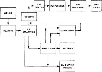
Figure 1-1. Gas field facility block diagram.
It is also possible that cooling may be necessary. Some gas reservoirs may be very deep and very hot. If a substantial amount of gas and liquid is being produced from the well, the flowing temperature of the well could be very hot even after the choke. In this case, the gas may have to be cooled prior to compression, treating, or dehydration. Separation and further liquid handling might be possible at high temperatures, so the liquids are normally separated from the gas prior to cooling to reduce the load on the cooling equipment. Heat exchangers are used to cool the gas and also to cool or heat fluids for treating water from oil, regenerating glycol and other gas treating fluids, etc.
In some fields, it may be necessary to provide heat during the early life of the wells when flowing-tubing pressures are high and there is a high temperature drop across the choke. Later on, if the wells produce more liquid and the flowing-tubing pressure decreases, it may be necessary to cool the gas. Liquids retain the reservoir heat better and have less of a temperature drop associated with a given pressure drop than gas.
Typically, in a gas facility, there is an initial separation at a high pressure, enabling reservoir energy to move the gas through the process to sales. It is very rare that the flowing-tubing pressure of a gas well, at least initially, is less than the gas sales pressure. With time, the flowing-tubing pressure may decline and compression may be needed prior to further handling of the gas. The initial separation is normally three-phase, as the separator size is dictated by gas capacity. That is, the separator will normally be large enough to provide sufficient liquid retention time for three-phase separation if it’s to be large enough to provide sufficient gas capacity. Selection and sizing of separators are described in Volume 1.
Liquid from the initial separator is stabilized either by multistage flash separation or by using a “condensate stabilization” process. Stabilization of the hydrocarbon liquid refers to the process of maximizing the recovery of intermediate hydrocarbon components (C3 to C6) from the liquid. Multistage flash stabilization is discussed in Volume 1. “Condensate stabilization,” which refers to a distillation process, is discussed in this volume.
Condensate and water can be separated and treated using processes and equipment described in Volume 1.
Depending on the number of stages, the gas that flashes in the lower pressure separators can be compressed and then recombined with the gas from the high-pressure separator. Both reciprocating and centrifugal compressors are commonly used. In low-horsepower installations, especially for compressing gas from stock tanks (vapor recovery), rotary and vane type compressors are common.
Gas transmission companies require that impurities be removed from gas they purchase. They recognize the need for removal for the efficient operation of their pipelines and their customers’ gas-burning equipment. Consequently, contracts for the sale of gas to transmission companies always contain provisions regarding the quality of the gas that is delivered to them, and periodic tests are made to ascertain that requirements are being fulfilled by the seller.
Acid gases, usually hydrogen sulfide (H2S) and carbon dioxide (CO2), are impurities that are frequently found in natural gas and may have to be removed. Both can be very corrosive, with CO2 forming carbonic acid in the presence of water and H2S potentially causing hydrogen embrittlement of steel. In addition, H2S is extremely toxic at very low concentrations. When the gas is sold, the purchaser specifies the maximum allowable concentration of CO2 and H2S. A normal limit for CO2 is between 2 and 4 volume percent, while H2S is normally limited to ¼ grain per 100 standard cubic feet (scf) or 4 ppm by volume.
Another common impurity of natural gas is nitrogen. Since nitrogen has essentially no calorific value, it lowers the heating value of gas. Gas purchasers may set a minimum limit of heating value (normally approximately 950 Btu/scf). In some cases it may be necessary to remove the nitrogen to satisfy this requirement. This is done in very low temperature plants or with permeable membranes. These processes are not discussed in this volume.
Natural gas produced from a well is usually saturated with water vapor. Most gas treating processes also leave the gas saturated with water vapor. The water vapor itself is not objectionable, but the liquid or solid phase of water that may occur when the gas is compressed or cooled is very troublesome. Liquid water accelerates corrosion of pipelines and other equipment; solid hydrates that can form when liquid water is present plug valves, fittings, and sometimes the pipeline itself; liquid water accumulates in low points of pipeline, reducing the capacity of the lines. Removal of the water vapor by dehydration eliminates these possible difficulties and is normally required by gas sales agreements. When gas is dehydrated its dewpoint (the temperature at which water will condense from the gas) is lowered.
A typical dehydration specification in the U.S. Gulf Coast is 7 lb of water vapor per MMscf of gas (7 lb/MMscf). This gives a dew point of around 32°F for 1,000 psi gas. In the northern areas of the U.S. and Canada the gas contracts require lower dew points or lower water vapor concentrations in the gas. Water vapor concentrations of 2-4 lb/MMscf are common. If the gas is to be processed at very low temperatures, as in a cryogenic gas plant, water vapor removal down to 1 ppm may be required.
Often the value received for gas depends on its heating value. However, if there is a market for ethane, propane, butane, etc., it may be economical to process these components from the gas even though this will lower the heating value of the gas. In some cases, where the gas sales pipeline supplies a residential or commercial area with fuel, and there isno plant to extract the high Btu components from the gas, the sales contract may limit the Btu content of the gas. The gas may then have to be processed to minimize its Btu content even if the extraction process by itself is not economically justified.
Chapter 9 discusses the refrigeration and cryogenic processes used to remove specific components from a gas stream, thereby reducing its Btu content.
Throughout the process in both oil and gas fields, care must be exercised to assure that the equipment is capable of withstanding the maximum pressures to which it could be subjected. Volume 1 discusses procedures for determining the wall thickness of pipe and specifying classes of fittings. This volume discusses procedures for choosing the wall thickness of pressure vessels. In either case, the final limit on the design pressure (maximum allowable working pressure) of any pipe/equipment system is set by a relief valve. For this reason, a section on pressure relief has been included.
Since safety considerations are so important in any facility design, Chapter 14 has been devoted to safety analysis and safety system design. (Volume 1, Chapter 13 discusses the need to communicate about a facility design by means of flowsheets and presents general comments and several examples of project management.)
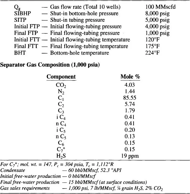
Table 1-1 describes a gas field. The example problems that are worked in many of the sections of this text are for sizing the individual pieces of equipment needed for this field.
Table 1-1 Example Field
* Reviewed for the 1999 edition by Folake A. Ayoola of Paragon Engineering Services, Inc.
CHAPTER 2 Heat Transfer Theory*
Many of the processes used in a gas-handling production facility require the transfer of heat....
Table of contents
- Cover Image
- Title page
- DISCLAIMER
- Copyright
- Acknowledgments
- Preface
- Table of Contents
- Chapter 1: Overview of Gas-Handling Facilities
- Chapter 2: Heat Transfer Theory
- Chapter 3: Heat Exchangers
- Chapter 4: Hydrates
- Chapter 5: LTX Units and Line Heaters
- Chapter 6: Condensate Stabilization
- Chapter 7: Acid Gas Treating
- Chapter 8: Gas Dehydration
- Chapter 9: Gas Processing
- Chapter 10: Compressors
- Chapter 11: Reciprocating Compressors
- Chapter 12: Mechanical Design of Pressure Vessels
- Chapter 13: Pressure Relief
- Chapter 14: Safety Systems
- Chapter 15: Valves, Fittings, and Piping Details
- Chapter 16: Prime Movers
- Chapter 17: Electrical Systems
- Index
- Surface Production Operations: Design of Gas-Handling Systems and Facilities
Frequently asked questions
Yes, you can cancel anytime from the Subscription tab in your account settings on the Perlego website. Your subscription will stay active until the end of your current billing period. Learn how to cancel your subscription
No, books cannot be downloaded as external files, such as PDFs, for use outside of Perlego. However, you can download books within the Perlego app for offline reading on mobile or tablet. Learn how to download books offline
Perlego offers two plans: Essential and Complete
- Essential is ideal for learners and professionals who enjoy exploring a wide range of subjects. Access the Essential Library with 800,000+ trusted titles and best-sellers across business, personal growth, and the humanities. Includes unlimited reading time and Standard Read Aloud voice.
- Complete: Perfect for advanced learners and researchers needing full, unrestricted access. Unlock 1.5M+ books across hundreds of subjects, including academic and specialized titles. The Complete Plan also includes advanced features like Premium Read Aloud and Research Assistant.
We are an online textbook subscription service, where you can get access to an entire online library for less than the price of a single book per month. With over 1.5 million books across 990+ topics, we’ve got you covered! Learn about our mission
Look out for the read-aloud symbol on your next book to see if you can listen to it. The read-aloud tool reads text aloud for you, highlighting the text as it is being read. You can pause it, speed it up and slow it down. Learn more about Read Aloud
Yes! You can use the Perlego app on both iOS and Android devices to read anytime, anywhere — even offline. Perfect for commutes or when you’re on the go.
Please note we cannot support devices running on iOS 13 and Android 7 or earlier. Learn more about using the app
Please note we cannot support devices running on iOS 13 and Android 7 or earlier. Learn more about using the app
Yes, you can access Surface Production Operations, Volume 2: by Ken Arnold,Maurice Stewart in PDF and/or ePUB format, as well as other popular books in Physical Sciences & Horticulture. We have over 1.5 million books available in our catalogue for you to explore.