- 416 pages
- English
- ePUB (mobile friendly)
- Available on iOS & Android
eBook - ePub
Electrochemical Reactions and Mechanisms in Organic Chemistry
About this book
Electrochemical reactions make significant contributions to organic synthesis either in the laboratory or on an industrial scale. These methods have the potential for developing more "green" chemical synthesis. Over recent years, modern investigations have clarified the mechanisms of important organic electrochemical reactions. Progress has also been made in controlling the reactivity of intermediates through either radical or ionic pathways. Now is the time to gather all the electrochemical work into a textbook.As an essential addition to the armory of synthetic organic chemists, electrochemical reactions give results not easily achieved by many other chemical routes. This book presents a logical development of reactions and mechanisms in organic electrochemistry at a level suited to research scientists and final year graduate students. It forms an excellent starting point from which synthetic organic chemists, in both academia and industry, can appreciate uses for electrochemical methods in their own work. The book is also a reference guide to the literature.
Trusted by 375,005 students
Access to over 1.5 million titles for a fair monthly price.
Study more efficiently using our study tools.
Information
Topic
Physical SciencesSubtopic
Organic ChemistryCHAPTER 1
ELECTROCHEMICAL OXIDATION AND REDUCTION OF ORGANIC COMPOUNDS
General Technique
During an electrochemical reaction, electrons are transferred between a molecule of the substrate and the electrode. Electrons are always transferred singly and the substrate first is converted to an intermediate with an unpaired electron. Transformation of this reactive intermediate to the final product involves a sequence of bond forming or bond cleaving reactions and frequently further single electron transfer steps. The complete electrochemical reaction vessel requires both an anode and a cathode. Only one of these electrodes, the working electrode, is involved with the chemical reaction of interest, oxidation at the anode or reduction at the cathode. The second electrode is the counter electrode and usually some simple inorganic reaction occurs here, such as hydrogen evolution if this is a cathode or oxygen evolution if this is an anode. The space between the anode and cathode is filled with an ionised salt solution and charge passes through the solution between the electrodes by migration of ions.
The simplest design of electrochemical cell has two electrodes dipping into the solution containing the substrate and the supporting electrolyte. A cell of this type is suitable for the Kolbe oxidation of carboxylate ions (see p. 316) where the anode reaction is given by Equation 1.1 and the cathode reaction is the evolution of hydrogen (Equation 1.2). Both the substrate and the hydrocarbon product are inert


towards reduction at the cathode.
For many processes, however, it is necessary to employ a divided cell in which the anode and cathode compartments are separated by a barrier, allowing the diffusion of ions but hindering transfer of reactants and products between compartments. This prevents undesirable side reactions. Good examples of the need for a divided cell are seen in the reduction of nitrobenzenes to phenylhydroxylamines (p. 379) or to anilines (p. 376). In these cases the reduction products are susceptible to oxidation and must be prevented from approaching the anode. The cell compartments can be divided with a porous separator constructed from sintered glass, porous porcelain or a sintered inert polymer such as polypropene or polytetrafluoroethene. Another type of separator uses woven polytetrafluoroethene cloth which has been exposed to a soluble silicate and dilute sulphuric acid so that silicic acid precipitates into the pores [1]. On a laboratory scale porous porcelain and sintered glass are the most commonly used materials.
On an industrial scale, ion-exchange membranes are most frequently used for the separator material [2]. Cationic and anionic types are both available and a sulphonated polytetrafluoroethene cation exchange resin, which can withstand aggressive conditions, is frequently used. Arrangements for sealing this type of separator into a laboratory scale glass cell are also available.
General purpose laboratory scale glass cells are either of the beaker-type (Figure 1.1a) or the H-type (Figure 1.1b). The early pioneers of organic electrochemistry used beaker-type cells, with cylindrical symmetry, and the separator was either a porous porcelain pot or a sintered glass disc [3]. Designs for beaker-type cells in more modern materials have been described [4]. The H-type cell can be designed to use either one or two sintered glass separators [5]. Oxygen must be excluded from the cathode compartment during electrochemical reduction otherwise current is consumed by the reduction of oxygen to water and the highly reactive superoxide anion is generated as an intermediate. A flow of inert gas is maintained in the cathode compartment. It is not essential to exclude oxygen during electrochemical oxidation but usually a flow of inert gas is maintained in the anode compartment so as to dilute any oxygen, which is evolved. A stirring device is necessary to decrease the thickness of the diffusion layer around the working electrode.
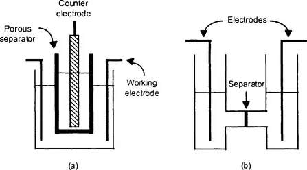
Figure 1.1 Cells used for laboratory scale electrochemical preparations: (a) a beaker-type cell; (b) an H-type cell.
The voltage drop across a working electrochemical cell is not uniformly distributed. This is shown schematically in Figure 1.2. A large proportion is due to the electrical resistance of the electrolyte and the separator. This, of course, can be decreased by a suitable cell design. The voltage drop across the working electrode solution interface determines the rate constant for the electrochemical reaction. It is often advantageous to maintain a constant potential drop across this interface to control the rate of unwanted side reactions. The working potential is measured relative to a reference electrode and probe, placed close to the working electrode surface. An aqueous saturated calomel electrode is the most frequently used reference. The relative potentials of other reference half-cells are given in Table 1.1. The reference electrode dips into a salt bridge containing the electrolyte used in the main electrochemical cell. The salt bridge can be terminated either by a thin Luggin-Harber capillary [6] placed close to the working electrode or by a plug of porous Vycor glass [7] or an inert fibre [8]. For non-aqueous electrochemistry IUPAC recommends the ferrocene-ferricinium couple as an internal reference standard of potential [9]. It is suitable for use in linear sweep and cyclic voltammetry but not for preparative scale experiments. The couple has potentials of +0.69 and +0.72 V vs. nhe in acetonitrile and dimethylformamide respectively [10].
TABLE 1.1
Potentials of some reference electrodes relative to either the standard hydrogen electrode or the saturated calomel electrode.
| Electrochemical cell | Potential / V | Ref. |
| (Pt)/H2, H3O+ (a = 1) || KC1 (satd.) / AgCl (satd.) /Ag | 0.199 | [12] |
| (Pt)/H2, H3O+ (a = 1) || KC1 (1.0 M) / Hg2Cl2(satd.) / Hg | 0.283 | [12] |
| (Pt)/H2, H3O+ (a = 1) || KC1 (satd.)/ Hg2Cl2 (satd.)./ Hg | 0.244 | [12] |
| Aqueous sce || 0.1 M NaClO4 in CH3CN || 0.01 M AgNO3 in CH3CN / Ag | 0.253 | [13] |
| Aqueous sce || 0.1 M Et1NClO4 || Me2CHO NaCl(satd.). CdCl2 (satd) / Cd, Hg | −0.737 | [14] |
| Aqueous sce || 0.1 Mu4I in 0.1 M Bu4NI in Mc2NCHO / Agl (sat.) / Ag | −0.32 | [15] |
| Aqueous sce || 0.1 M Et1NI in Me2CHO / Agl (satd.) / Ag | −0.638 | [16] |
Further data in ref. [17].
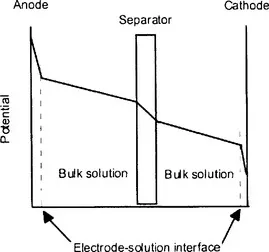
Figure 1.2 Distribution of potential across a working electrochemical cell. The potential drop across the working electrode-solution interface drives the cell reaction.
There is a potential drop V across the solution between the layer around the working electrode and the tip of the reference probe. This is related to the separation distance d by Equation 1.3 where i is the current flowing through the c...
Table of contents
- Cover image
- Title page
- Table of Contents
- Copyright
- Dedication
- PREFACE
- Chapter 1: ELECTROCHEMICAL OXIDATION AND REDUCTION OF ORGANIC COMPOUNDS
- Chapter 2: OXIDATION OF ALKANES, HALOALKANES AND ALKENES
- Chapter 3: REDUCTION OF ALKENES AND CONJUGATED ALKENES
- Chapter 4: REDUCTIVE BOND CLEAVAGE PROCESSES - I
- Chapter 5: REDUCTIVE BOND CLEAVAGE PROCESSES - II
- Chapter 6: OXIDATION OF AROMATIC RINGS
- Chapter 7: REDUCTION OF AROMATIC RINGS
- Chapter 8: OXIDATION OF ALCOHOLS, AMINES AND AMIDES
- Chapter 9: OXIDATION OF KETONES, ALDEHYDES, AND CARBOXYLIC ACIDS
- Chapter 10: REDUCTION OF CARBONYL COMPOUNDS, CARBOXYLIC ACIDS AND THEIR DERIVATIVES
- Chapter 11: REDUCTION OF NITRO, NITROSO, AZO AND AZOXY GROUPS
- INDEX
Frequently asked questions
Yes, you can cancel anytime from the Subscription tab in your account settings on the Perlego website. Your subscription will stay active until the end of your current billing period. Learn how to cancel your subscription
No, books cannot be downloaded as external files, such as PDFs, for use outside of Perlego. However, you can download books within the Perlego app for offline reading on mobile or tablet. Learn how to download books offline
Perlego offers two plans: Essential and Complete
- Essential is ideal for learners and professionals who enjoy exploring a wide range of subjects. Access the Essential Library with 800,000+ trusted titles and best-sellers across business, personal growth, and the humanities. Includes unlimited reading time and Standard Read Aloud voice.
- Complete: Perfect for advanced learners and researchers needing full, unrestricted access. Unlock 1.5M+ books across hundreds of subjects, including academic and specialized titles. The Complete Plan also includes advanced features like Premium Read Aloud and Research Assistant.
We are an online textbook subscription service, where you can get access to an entire online library for less than the price of a single book per month. With over 1.5 million books across 990+ topics, we’ve got you covered! Learn about our mission
Look out for the read-aloud symbol on your next book to see if you can listen to it. The read-aloud tool reads text aloud for you, highlighting the text as it is being read. You can pause it, speed it up and slow it down. Learn more about Read Aloud
Yes! You can use the Perlego app on both iOS and Android devices to read anytime, anywhere — even offline. Perfect for commutes or when you’re on the go.
Please note we cannot support devices running on iOS 13 and Android 7 or earlier. Learn more about using the app
Please note we cannot support devices running on iOS 13 and Android 7 or earlier. Learn more about using the app
Yes, you can access Electrochemical Reactions and Mechanisms in Organic Chemistry by J. Grimshaw in PDF and/or ePUB format, as well as other popular books in Physical Sciences & Organic Chemistry. We have over 1.5 million books available in our catalogue for you to explore.