RF and mm-Wave Power Generation in Silicon presents the challenges and solutions of designing power amplifiers at RF and mm-Wave frequencies in a silicon-based process technology. It covers practical power amplifier design methodologies, energy- and spectrum-efficient power amplifier design examples in the RF frequency for cellular and wireless connectivity applications, and power amplifier and power generation designs for enabling new communication and sensing applications in the mm-Wave and THz frequencies.
With this book you will learn:
- Power amplifier design fundamentals and methodologies
- Latest advances in silicon-based RF power amplifier architectures and designs and their integration in wireless communication systems
- State-of-the-art mm-Wave/THz power amplifier and power generation circuits and systems in silicon
- Extensive coverage from fundamentals to advanced design topics, focusing on various layers of abstraction: from device modeling and circuit design strategy to advanced digital and mixed-signal architectures for highly efficient and linear power amplifiers
- New architectures for power amplifiers in the cellar and wireless connectivity covering detailed design methodologies and state-of-the-art performances
- Detailed design techniques, trade-off analysis and design examples for efficiency enhancement at power back-off and linear amplification for spectrally-efficient non-constant envelope modulations
- Extensive coverage of mm-Wave power-generation techniques from the early days of the 60 GHz research to current state-of the-art reconfigurable, digital mm-Wave PA architectures
- Detailed analysis of power generation challenges in the higher mm-Wave and THz frequencies and novel technical solutions for a wide range for potential applications, including ultrafast wireless communication to sensing, imaging and spectroscopy
- Contributions from the world-class experts from both academia and industry
Trusted by 375,005 students
Access to over 1.5 million titles for a fair monthly price.
Hua Wang1 and Kaushik Sengupta2, 1School of Electrical and Computer Engineering, Georgia Institute of Technology, Atlanta, GA, USA, 2Department of Electrical Engineering, School of Engineering and Applied Science, Princeton University, Princeton, NJ, USA
The ever-growing demand for higher data-rate, energy efficiency, and performance robustness has posed increasingly stringent requirements on wireless transceiver systems. This is particularly true for mobile devices for consumer electronics and field-deployable systems in defense-related applications, where improving system size, weight and power, enhancing wireless connectivity performance and robustness, and extending the system battery life and efficiency are the primary focus points.
The power amplifier (PA) is often considered one of the most critical building blocks in a wireless transceiver system. It serves as the interface between the radio-frequency (RF)/mm-Wave electronics system for electrical signal generation and conditioning and the antenna structure for electromagnetic signal radiation. It amplifies or generates the transmitted high-frequency signal to the proper power level for the desired wireless transmission and conditions the transmitted signal to satisfy spectrum mask compliance. PA’s performance has critical impact on the entire transmitter (TX) system, including the TX output power level, energy efficiency, bandwidth, signal fidelity, and spectrum management, all of which govern the overall quality-of-service (QoS) of the wireless link (Table 1.1) [1,2]. Moreover, due to their large-signal and high-power operations at RF or mm-Wave frequencies, PAs often encounter unique design challenges and trade-offs that are substantially different compared with small-signal linear circuits and deserve specialized and holistic design considerations [3,4].
Table 1.1
PA Performance Metrics and the Corresponding TRX Performance
PA Metrics
TRX Performance
Output power
Link budget
Peak power efficiency
Power consumption/battery life
Back-off power efficiency (large PAPR)
Power consumption/battery life
Signal fidelity/linearity (amplitude/phase)
Data error rate/spectrum compliance
Noise floor and TX leakage
Spectrum compliance
Bandwidth
Data rate/frequency agility
Robustness against antenna mismatches
Wireless link robustness
Module size and cost
TRX system size, cost, and packaging complexity
This chapter serves as the introduction to this book. We will start with presenting the key PA performance metrics and how they impact the overall transceiver system. Then, we will discuss different technology platforms for implementing PAs. In particular, we will focus on the unique advantages and challenges of utilizing silicon integrated circuit (IC) processes to implement PAs for wireless transceiver systems, or in more general sense, power-generation circuits, at RF/mm-Wave frequencies. Next, current technologies and research trends will be presented. To better demonstrate these trends in silicon-based PAs, the following chapters of this book present state-of-the-art designs contributed from world-class experts, from academia and industry. At the end of this introductory chapter, we will give a brief summary of the technical contents of the following chapters to better guide the readers.
1.1 What Are the Key PA Performance Metrics?
Table 1.1 summarizes the PA performance metrics and their impact on transceiver system performance.
1.1.1 PA Output Power
The PA output power level directly governs the transmitter power, which is an important aspect in estimating the wireless system link budget and the effective communication range [1]. The link budget equation can be expressed as
(1.1)
(1.1)
where
is the received power;
is the transmitted (PA output) power;
and
are the transmitter (TX) and receiver (RX) loss capturing the passive network loss between the TX/RX and the antennas;
and
are the transmitter and receiver antenna gain. The term
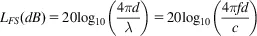
stands for the free space loss or path loss, which can be computed using Friis transmission equation as
(1.2)
(1.2)
where d is the communication distance;
and
are the wavelength and frequency of the carrier signal respectively; c stands for the speed of light in the transmission medium. Further, in a practical wireless communication channel, there could be additional losses due to scattering, multi-path, slow and fast fading. For a given wireless application, the power requirement for the PA can be determined by the minimum power requirement for the receiver to process the wireless data. Assuming the receiver is noise-limited, the minimum required receiver power
can be estimated based on the receiver sensitivity as
(1.3)
(1.3)
where BW is the receiver bandwidth, NF is the receiver noise figure and SNRmin is the minimum SNR needed at the receiver front-end to maintain the bit-error rate for the given signal modulation scheme. Therefore, given the target wireless application, one can calculate the required transmitter power
to achieve a quality communication link over the desired wireless transmission distance. In addition, the transmitted signal should also comply with the corresponding spectral mask defined by the specific wireless standard to ensure minimal in-band and adjacent-channel interference with concurrent wireless users.
1.1.2 PA Power Efficiency
The power efficiency of the PA determines its DC power consumption, which often dominates the total power consumption of the transmitter system and directly affects battery lifetime. In addition, a significant portion of the DC power is dissipated as heat which also sets the thermal handling requirement on the transceiver system packaging [5–7]. In many high-power applications, thermal handling requires the use of cooling technology which greatly affect the total cost and form-factor of the wireless transceiver system. In addition, thermal handling should also be properly addressed to avoid thermal-related stress and memory effects to the PA module.
To evaluate the PA’s capability of converting DC power to the desired RF power, one can use the metric PA drain efficiency (DE) defined as
(1.4)
(1.4)
where
is the PA’s output power and
is the PA’s DC power consumption. Note that this PA DE metric can be generalized to be used to describe the energy-conversion efficiency in high-frequency oscillators in mm-Wave/THz circuits and systems, as will be discussed in chapters 17–19.
To account for the power gain of the PA, one may use PA power-added efficiency (PAE) defined as
Table of contents
Cover image
Title page
Table of Contents
Copyright
List of Contributors
Biography
Acknowledgment
Chapter 1. Introduction
Part I: Power amplifier design methodologies
Part II: RF Power Amplifier Design Examples
Part III: mm-Wave and Terahertz Power Generation Design Examples
Index
Frequently asked questions
Yes, you can cancel anytime from the Subscription tab in your account settings on the Perlego website. Your subscription will stay active until the end of your current billing period. Learn how to cancel your subscription
No, books cannot be downloaded as external files, such as PDFs, for use outside of Perlego. However, you can download books within the Perlego app for offline reading on mobile or tablet. Learn how to download books offline
Perlego offers two plans: Essential and Complete
Essential is ideal for learners and professionals who enjoy exploring a wide range of subjects. Access the Essential Library with 800,000+ trusted titles and best-sellers across business, personal growth, and the humanities. Includes unlimited reading time and Standard Read Aloud voice.
Complete: Perfect for advanced learners and researchers needing full, unrestricted access. Unlock 1.5M+ books across hundreds of subjects, including academic and specialized titles. The Complete Plan also includes advanced features like Premium Read Aloud and Research Assistant.
Both plans are available with monthly, semester, or annual billing cycles.
We are an online textbook subscription service, where you can get access to an entire online library for less than the price of a single book per month. With over 1.5 million books across 990+ topics, we’ve got you covered! Learn about our mission
Look out for the read-aloud symbol on your next book to see if you can listen to it. The read-aloud tool reads text aloud for you, highlighting the text as it is being read. You can pause it, speed it up and slow it down. Learn more about Read Aloud
Yes! You can use the Perlego app on both iOS and Android devices to read anytime, anywhere — even offline. Perfect for commutes or when you’re on the go. Please note we cannot support devices running on iOS 13 and Android 7 or earlier. Learn more about using the app
Yes, you can access RF and mm-Wave Power Generation in Silicon by Hua Wang,Kaushik Sengupta in PDF and/or ePUB format, as well as other popular books in Technology & Engineering & Industrial Design. We have over 1.5 million books available in our catalogue for you to explore.