eBook - ePub
Advanced Techniques for Assessment Surface Topography
Development of a Basis for 3D Surface Texture Standards "Surfstand"
- 340 pages
- English
- ePUB (mobile friendly)
- Available on iOS & Android
eBook - ePub
Advanced Techniques for Assessment Surface Topography
Development of a Basis for 3D Surface Texture Standards "Surfstand"
About this book
This publication deals with the latest developments in the field of 3D surface metrology and will become a seminal text in this important area. It has been prepared with the support of the European Community's Directorate General XII and represents the culmination of research conducted by 11 international partners as part of an EU-funded project. The aim of the project is to inform standards bodies of the possibilities that exist for a new international standard covering the field of 3D surface characterisation.The book covers a description of the proposed 3D surface parameters and advanced filtering techniques using wavelet and robust Gaussian methodologies. The next generation areal surface characterisation theories are discussed and their practical implementation is illustrated. It describes techniques for calibration of 3D instrumentation, including stylus instruments as well as scanning probe instrumentation. Practical verification of the 3D parameters and the filtering is illustrated through a series of case studies which cover bio-implant surfaces, automotive cylinder liner and steel sheet. Finally, future developments of the subject are alluded to and implications for future standardisation and development are discussed.
Trusted by 375,005 students
Access to over 1.5 million titles for a fair monthly price.
Study more efficiently using our study tools.
Information
1
Introduction: The History and Current State of 3D Surface Characterisation
Liam Blunt, Taylor Hobson Professor of Surface Metrology, School of Engineering, University of Huddersfield, UK
1.1 Defining the nature of a surface
An appropriate question at the beginning of a text like this might be “what is a surface?”. The answer to this question is not simple, though considering a surface as a boundary is a good start. Bearing this in mind, the surface of an engineering component can therefore be thought of as the physical boundary between the work piece and the surrounding environment.
The real surface of a workpiece has been defined in international standards (ISO) as:
A set of features which physically exist and separate the entire workpiece from the surrounding medium (ISO 14460-1)[1].
It would be false to assume that the surface of a workpiece is invariably mechanical in nature. In fact the electromagnetic surface of a workpiece is an equally valid concept. The definitions ISO 16610-1, of both are rather cumbersome but are given below.
Real surface of a workpiece (mechanical)
Boundary of the erosion, by a spherical ball of radius r, of the locus of the centre of an ideal tactile sphere, also with radius r, rolled over the real surface of a workpiece.
Real surface of a workpiece (electro-magnetic)
Locus of the effective ideal reflection point of the real surface of a workpiece, by electromagnetic radiation with a specified wavelength.
For most purposes, however, especially where the workpiece interacts with its working environment through some form of mechanical contact it is the mechanical surface that is of interest. This is the surface that is measured using standard surface metrology techniques and it is this surface that is referred to on engineering drawings of components to be manufactured.
A further rhetorical question might be, why are we interested in surfaces? The clear reason is that it has been shown that 90% of all engineering component failures in practice are surface initiated, through mechanisms such as fatigue cracking, stress corrosion cracking, fretting wear, excessive abrasive or adhesive wear, corrosion, erosion etc. Clearly then, it is important to understand the properties of the surface and near surface zones of a component. These properties can be grouped together under the term surface integrity [2].
A glance at the nominal technical drawing of an engineering component clearly shows that the drawing assumes that each surface of the component is perfectly smooth, straight, clean and free from defects. There is an assumption that the manufacturing engineer can achieve this using the techniques at his disposal. This surface, the one assumed by the drawing is called the nominal surface. The manufacturing engineer now studies the drawing and attempts to manufacture the component to the specified dimensions within the tolerance limits. When manufacturing the component the engineer knows that it is impossible to manufacture a perfectly smooth surface, as the particular manufacturing method chosen will leave a micro-scale “fingerprint” on the surface which is unique to that manufacturing process. The nature of that “fingerprint” is referred to as the surface texture or surface topography of the component. Normally, this consists of a series of peaks and valleys that have characteristic shape size and spacing.
As well as affecting the shape of the surface texture the manufacturing method chosen also affects the layers directly below the surface of the component. For example, if we take the machined surface of a metal such as steel and take a cross section through the surface we can see the surface is made up of a number of layers (Figure 1.1).
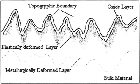
Figure 1.1 Schematic cross sectional view of a surface showing the surface and sub surface layers
These layers consist of:
• An oxide layer, which all metals possess, this layer being several nanometers thick.
• The topographic layer, the hills and valleys that make up the shape of the surface. These result from the material removal (or addition) process and are produced by the unit manufacturing process (tool passage, electrical discharge, plating process etc.).
• A plastically deformed layer produced by the machining operation.
• A metallurgically deformed layer resulting primarily from heating during machining.
• The bulk material.
Figure 1.2 shows an example of a cross section through (a) an abusively ground steel surface, and (b) a gently ground steel surface. What is clear from the image is the distinct layering of the surface zone and also how the severity of the grinding operation has affected the surface layers and the surface roughness.
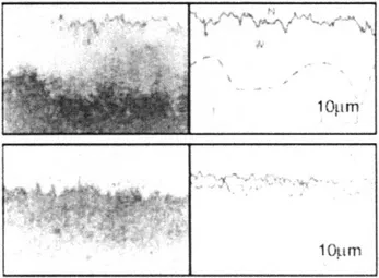
Figure 1.2 Ground surface cross section a) abusively ground b) gently ground
Whilst the sub surface layers are critically important, they are very difficult to measure without destroying the component. Therefore engineers have concentrated on measuring the surface roughness as both a means of quality assurance and as a means of inferring functional performance. The geometrical form of any surface is usually referred to as the surface texture. Conventionally the texture is made up of features defined as roughness, waviness and form (Figure 1.3). Traditionally, when the surface texture is quantitatively measured it is only the roughness that is analysed and the waviness and form elements are mechanically, electrically or digitally filtered out from the recorded data.
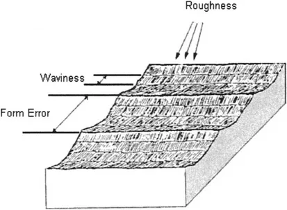
Figure 1.3 Roughness, waviness and form of an engineering surface [3]
The difference between the roughness, waviness and form characteristics of the surface texture is based on the surface wavelength or peak to peak spacing. The great problem with these conventional definitions is that the point at which roughness becomes waviness (cut off) is arbitrary and is usually related to the manufacturing process from which the surface derived or from the intended function of the workpiece. For example, what would be considered as roughness on an automobile axle would be considered waviness of form error on a watch spindle [3].
As a rule roughness can be considered as being produced by the method of manufacture rather than the machine, and constitutes tool or grit marks and is usually of a periodic nature. On a finer scale there is tearing of material, as a result of built up edge formation and tool tip irregularities. Waviness is usually attributed to an individual machine, for example an unbalanced grinding wheel, tool feed irregularities and general chatter vibrations. Form errors are usually caused by a lack of rigidity of the workpiece during the machining operation allowing it to flex or bend. Slide way undulation can also cause form error. Strains in the material, surface induced trough heating or excessive surface residual stress can cause flexure and form error. Usually, form errors produce only one or two undulations over the dimensions of the assessed surface.
1.2 Surface creation
Surfaces are created by a large variety of manufacturing processes and each manufacturing technique leaves its own fingerprint on the surface produced. Sometimes, the fingerprint from a surface can produce a beneficial effect on the character of the surface but on other occasions the resulting surface can deleteriously affect the ability of the surface to perform its intended function. It is therefore important that the “fingerprint” which is produced as a result of any surface manufacturing method be understood in terms of its effect on the function for which the surface is intended. If the general nature of the surface is deemed unacceptable then a surface modification technique should be undertaken to modify its suitability for the intended function. In many cases it is not the inherent nature of the machining process that is at fault but the machining conditions under which the surface has been finished. As a consequence, modifying the parameters of the final process may yield a satisfactory result. This implies that the engineer must improve his understanding of surface production methods and the effects that these production methods may have on the functional properties of the surface.
Many surfaces are designed to interact with other solids and as a consequence are sometimes subjected to surface treatments that alter the properties of the surface layers. The processes most often used are plating, blasting, peening, carburising, nitriding, ion implantation etc. these treatments produce the so-called “functional surfaces”. The relationship between surface topography and the functional surface has only been partially investigated and the most work that has been conducted in this area was undertaken using 2D surface analysis, using profile analysis or through the application and interpretation of auto-correlation functions.
1.3 Evolution of assessment
The earliest assessments of surface finish were made simply by running a fingernail across the surface. This technique survives to this day as tactile comparison, where the finish of the workpiece is compared manually with a set of calibrated surfaces of different known roughnesses produced by the same finishing process [4].
The first quantitative measuring instrument was the light-section microscope, developed by Gustav Schmaltz in Germany early in the 20th Century [5]. An image of an illuminated slit was projected on the workpiece at an angle to the vertical, and the distortions in its reflection magnified the surface irregularities. Peak and valley heights could then be read off the calibrated eyepiece.
The subject of surface finish assessment began properly when Professor Schmaltz developed a simple profilometer to enable the deviations on a selected line of a surface to be measured and recorded. This process was simply achieved by drawing a stylus across a surface and recording the vertical deviations of the surface that had been suitably differentially magnified by an optical lever (the vertical magnification being greater than the horizon). The magnified image was recorded on photosensitive paper and was presented in a partial circular arc since the screen was rotated as the stylus progressed across the surface. This simple mechanical process enabled the roughness to be measured in terms of peak to valley deviat...
Table of contents
- Cover image
- Title page
- Table of Contents
- Copyright
- Acknowledgements
- Chapter 1: Introduction: The History and Current State of 3D Surface Characterisation
- Part 1: Characterisation
- Part 2: Instrumentation
- Part 3: Case Studies
- Part 4: Future Developments
- Index
Frequently asked questions
Yes, you can cancel anytime from the Subscription tab in your account settings on the Perlego website. Your subscription will stay active until the end of your current billing period. Learn how to cancel your subscription
No, books cannot be downloaded as external files, such as PDFs, for use outside of Perlego. However, you can download books within the Perlego app for offline reading on mobile or tablet. Learn how to download books offline
Perlego offers two plans: Essential and Complete
- Essential is ideal for learners and professionals who enjoy exploring a wide range of subjects. Access the Essential Library with 800,000+ trusted titles and best-sellers across business, personal growth, and the humanities. Includes unlimited reading time and Standard Read Aloud voice.
- Complete: Perfect for advanced learners and researchers needing full, unrestricted access. Unlock 1.5M+ books across hundreds of subjects, including academic and specialized titles. The Complete Plan also includes advanced features like Premium Read Aloud and Research Assistant.
We are an online textbook subscription service, where you can get access to an entire online library for less than the price of a single book per month. With over 1.5 million books across 990+ topics, we’ve got you covered! Learn about our mission
Look out for the read-aloud symbol on your next book to see if you can listen to it. The read-aloud tool reads text aloud for you, highlighting the text as it is being read. You can pause it, speed it up and slow it down. Learn more about Read Aloud
Yes! You can use the Perlego app on both iOS and Android devices to read anytime, anywhere — even offline. Perfect for commutes or when you’re on the go.
Please note we cannot support devices running on iOS 13 and Android 7 or earlier. Learn more about using the app
Please note we cannot support devices running on iOS 13 and Android 7 or earlier. Learn more about using the app
Yes, you can access Advanced Techniques for Assessment Surface Topography by Liam Blunt,Xiang Jiang in PDF and/or ePUB format, as well as other popular books in Physical Sciences & Physics. We have over 1.5 million books available in our catalogue for you to explore.