
- English
- ePUB (mobile friendly)
- Available on iOS & Android
About this book
Designed to provide an insight into the Mechanical Design concept.The book promises to make you understand and practice the SolidWorks framework. The aim of this book is to take you on a journey to all the phases of SolidWorks. SolidWorks is an innovative, next-generation industry software that allows you to solve and understand the designing and mechanical problems. SolidWorks uses a technical implementation approach for sketching, surfacing, and sheet metal drafting in an incremental and easy way. The main objective of this book is to make the reader understand the concepts of design based on practical knowledge rather than theoretical knowledge. KEY FEATURES• Each command is explained in a simple and understandable manner• Step-by-step explanation• Practical knowledge rather than theoretical knowledge• Covers all the modules of SolidWorks 2019 WHAT WILL YOU LEARN• SolidWorks and its GUI• Sketches (Line, Rectangle, Slot, Circle, ARC, Polygon, and Spline)• Extrude, Revolved, Swept, Loft, Boundary, Filt, and Chamfer)• Surface (Extruded, Revolved, Swept, Lofted, Boundary, Filled, and Planner)• Sheet metal (Base flange/tab, Edge flange, Miter flange, and Hem)• Weldments (Structural member, Trim/Extend, End cap, and Gusset)• Curves• Mold design• Drafting• Assembly WHO THIS BOOK IS FORMechanical engineers and designers, automobile engineers, product designers, heavy vehicle designers.AUTHOR BIOLinkan Sagar has done B.tech from UPTU, Lucknow. He has extensively worked on various software like solidworks, catia, staad-pro, and revit. He is having wide industry experience and worked on more than 18 major live projects. He has delivered approximately 280 presentation in sector of engineering and designing.His Linkedin: linkedin.com/in/linkan-sagar-4b16a7a7
Tools to learn more effectively

Saving Books

Keyword Search

Annotating Text

Listen to it instead
Information
CHAPTER 1
Introduction and Overview
What is SolidWorks?
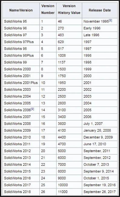
Stating of SolidWorks?
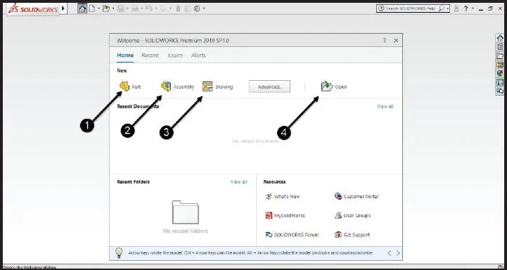
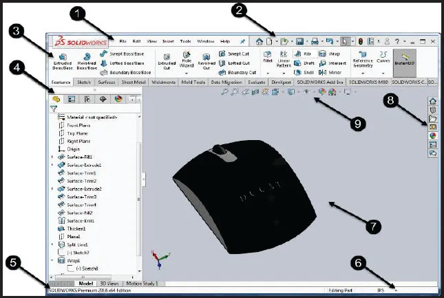
GUI of SolidWorks
- Menu Bar: It is a normal toolbar. All tools are there in it. There are many tools like File, Edit, View, Insert, Tools, and so on. Usually it is used to find those tools which you cannot find out elsewhere, but you can find in this Menu bar.
- Quick access tool: It is used to use some tools which are used mostly for short time. You can do all the settings of SolidWorks like page setup.
- Command Manager: It is present in Ribbon bar, there are every tool present which are used to create drawing. There are many different tabs like Sketch, Features, Surface, Sheet metal and Weldment, and so on. When you work on any Module, you can select the required tab and if there is no module you can right click on the tab and you can select any module which you want.
- Feature Manager Design Tree: Design tree is used to create or modify design. It has advantage that you can modify the tool of any design, sketch or tool of module used in it.
- Status bar: Status bar is used as command bar which helps in telling the steps.
- Unit: You can set the unit for drawing directly from here.
- Graphics area: Graphic area is a drawing area which is used to create the drawing.
- Resources: It is used for the library of material, view palette and design.
- View toolbar: View toolbar is used to show view of page or design view like view side, section view and visual style, and so on.
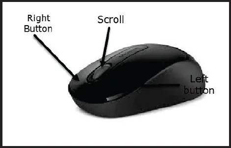
Mouse Handling
- Left button is used to select the object, or you can click anywhere.
- The right button is used to get additional options such as hiding the object and the normal view option.
- Scroll is used to zoom in or zoom out the page, by scrolling it forward or backward.
- Scroll is also used to rotate the page by pressing and moving it.
View Tool
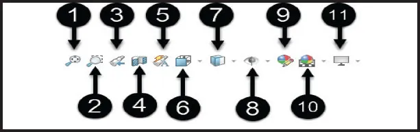
- Zoom to fit: It is used to fit the drawing in drawing area.
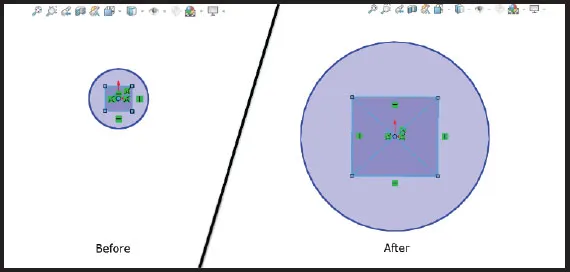 Figure 6 Zoom image
 - Zoom to area: It is used for zooming that particular area which you want to zoom. For this, first you need to select the first corner of that area and then the opposite one.
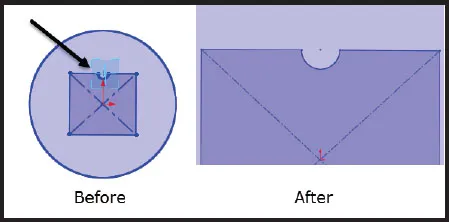 Figure 7 Zoom area image
 - Previous view: It is used to change the current view to get the previous view. Suppose you create a sketch and set the front view for this and you rotate the sketch now you want to see the front view so you can click on front view icon to see that view.
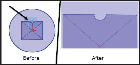 Figure 8 Pervious view image
 - Section view: It is used to get the interior view of any part by cutting it. Section can be seen from any view like any plane or side view. (Note: If you want to change the plane, you can change it from the section view tab.)
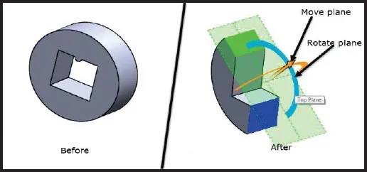 Figure 9 section view
 - Dynamic annotation view: It is used when you already give the dimensions to the part on the current view and you rotate the part and now come back to the previous view to get the existing dimensions. When you come to the actual view, dimension will automatically show.
 Figure 10 Dynamic annotation view
 - View Orientation: It is used to show any side of object like front view, top view, left view, right view, isolated view, and so on. and it is also used to set the multiple view of drawing area like you can create four view in one time in which you can show diffe...
Table of contents
- Cover Page
- Title Page
- Copyright Page
- Preface
- Acknowledgement
- About the Author
- Table of Contents
- 1. Introduction and Overview
- 2. Sketch
- 3. Features
- 4. Surface
- 5. Sheet Metal
- 6. Weldments
- 7. Curves
- 8. Mold Design
- 9. Assembly
- 10. Drafting
Frequently asked questions
- Essential is ideal for learners and professionals who enjoy exploring a wide range of subjects. Access the Essential Library with 800,000+ trusted titles and best-sellers across business, personal growth, and the humanities. Includes unlimited reading time and Standard Read Aloud voice.
- Complete: Perfect for advanced learners and researchers needing full, unrestricted access. Unlock 1.4M+ books across hundreds of subjects, including academic and specialized titles. The Complete Plan also includes advanced features like Premium Read Aloud and Research Assistant.
Please note we cannot support devices running on iOS 13 and Android 7 or earlier. Learn more about using the app