
- 142 pages
- English
- ePUB (mobile friendly)
- Available on iOS & Android
eBook - ePub
Military Metallurgy
About this book
This book gives a broad based view of metals in military service, covering several examples and rationales. It is useful for the militarist and for the metallurgist or materials scientist. The content of the book is based on course notes compiled for undergraduate and post-graduate students.
Tools to learn more effectively

Saving Books

Keyword Search

Annotating Text

Listen to it instead
Information
1
Introduction to Metallurgy and Materials Selection
The science and technology of metals is diverse, covering aspects such as: extraction from ores, refining, alloying, castings and ingot production, primary production, secondary production to semi-finished products, heat treatment, quality control, mechanical property measurement, study of microstructures (using microscopes), atomic structure, materials selection, joining, machining, wear, corrosion, fatigue, environmental effects on mechanical properties, failure and fractography, and recycling of scrap. In this book, depending on the military example being discussed, some of these aspects will scarcely be mentioned - but the areas of mechanical properties, microstructure and materials selection keep recurring, and these are now introduced.
MECHANICAL PROPERTIES AND THEIR MEASUREMENT
Selecting the right materials is critical for the correct functioning of any engineering device, and this requires an understanding of their mechanical properties. The most common mechanical tests are now considered:
The Tensile Test to measure strength and ductility
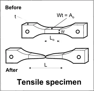
A tensile specimen is dogbone shaped, either round or flat in section as seen in Plate 1. A flat specimen is shown here ‘before’ and ‘after’ testing. The central parallel portion, the ‘gauge’, is where most deformation occurs and lines are drawn to give the original gauge length L0. The original cross-sectional area bearing the tensile force is A0 - the original specimen width times its thickness Wt in mm2 units. After the test the broken two parts of the specimen are reconstituted to measure the final gauge length L and estimate ductility. A typical tensile test machine (tensometer) is shown in Plate 2.
The specimen heads are loaded into the tensometer grips and the specimen pulled to failure - usually at a crosshead speed of around 10 mm per minute (10 mm min1). Force is monitored by a load cell attached to one of the grips.
The X-Y recorder on the tensometer plots a force versus extension curve, which can then be rationalised to give a tensile stress-strain curve, so that values can be related to any size of component. Engineering stress (σ) is force/A0 in N mm2, MN m2, or MPa units, and all three are numerically equivalent. Engineering strain (e) is extension/L0 which is dimensionless (mm/mm). These both relate to the original dimensions of the specimen which is very convenient. Sometimes true stress (force/A) and true strain ‘ℇ’ [ln(L/Lo)] are used, A and L being instantaneous values requiring an extensometer to be attached to the specimen.
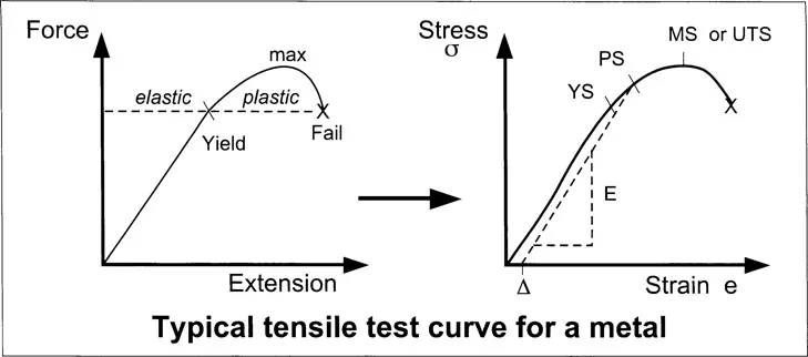
Initial loading is linear elastic, and this is reversible such that subsequent unloading will return the specimen to its original dimensions. The design engineer will usually try to choose a component cross-section such that the highest expected service stress is lower than the yield stress and by a reasonable safety factor. However, if the yield stress is exceeded then plastic or permanent deformation results. The engineering stress peaks at the maximum stress (MS) before dropping off to fracture, and this is due to localised ‘necking’ of the specimen - true stress climbs all the way to fracture.
Strength parameters measured in the tensile test are maximum stress MS, or ultimate tensile stress UTS as it is more usually called, and yield stress YS. Sometimes the limit of linearity is difficult to ascertain and a proof stress is measured instead by projecting an offset (∆) up parallel to the elastic loading ramp - eg 0.2%PS, where the offset is 0.2% of the gauge length. The offset can vary, usually between 0.1% and 2% of the gauge length, but all proof stress values are in excess of the yield stress.
Commercially pure aluminium would give tensile values of about 40 MPa YS and 90 MPa UTS, while ultra-high strength maraging steel would return values of around 2000 MPa YS and 2100 MPa UTS.
Tensile Stiffness or Young’s modulus (E) is the slope of the elastic line, but this can be difficult to measure accurately because of test machine compliance. For metals, Young’s modulus varies from about 70 GPa for aluminium alloys to around 210 GPa for steels.
Ductility is defined as % elongation to fracture %E1 which is 100 x (L-L0)/L0. A ductile alloy such as cartridge brass will give a value of about 65 %E1. A thermosoftening polymer such as polythene can easily give a tensile ductility value of 500 %E1. Most ceramics have very limited ductility (<2 %E1) and their tensile properties have to be measured via bend testing.
Ductility can often be inferred from fracture appearance. For instance the burst general purpose machine gun barrel GPMG in Plate 3 reveals much plasticity and so the heat treated low alloy steel used to make it is clearly fairly ductile. On the other hand the ‘hogging’ fracture of the hull of SS Schenectady in Plate 4 is macroscopically brittle - one can almost imagine weld repairing it in dry-dock without the need for much filler metal! This mode of failure was not uncommon in the Liberty ships of World War II as they crossed the Atlantic, often in winter making the likelihood of brittle fracture worse. They were amongst the first all-welded vessels, and grain growth in the weld heat affected zones HAZ was blamed. Afterwards the manganese content of weldable steels was increased to counteract this effect. The term brittle is used ambiguously by metallurgists. It is used to mean low ductility and also to mean low toughness, but the two are not always synonymous.
Toughness is defined as the energy to fracture Ef - units Nm or J. The area under the tensile curve is the energy to fail per unit gauge volume, and is a measure of toughness at slow strain rate - de/dt or ė, in mm/mm per second or s−1. The initial strain rate is given by V/L0 where V is the crosshead speed, and for a 20 mm gauge length pulled at a crosshead speed of 10 mm min1 this is about 8.103 s−1. However, in practice toughness is usually measured at higher strain rate, as in the impact test.
The Impact Test to measure comparative impact toughness
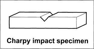
The most common impact specimen is the Charpy specimen, measuring 55 mm long by 10 mm square and with a 2 mm deep V-notch as a crack starter - seen in Plate 1 and drawn here. This is placed in the 40 mm gap in the anvil at the bottom of the Charpy pendulum machine shown in Plate 5, with the notch facing out. Then the raised pendulum (with a tup mass of about 22 kg) is released to strike the specimen with 300 J energy at an impact speed of 5 ms1 - giving a strain rate at the notch root of around 3.102 s1. The dial is calibrated to give a direct reading of energy to fracture (Ef) making the test quick, easy to perform, and ideal for quality control purposes. However, this test only gives comparative impact toughness values for specimens tested with this particular specimen geometry and in this particular way. For instance doubling the area of metal underneath the notch does not give twice the original Ef value, and altering the shape of the notch can cause the toughness ‘league table’ to change.
Charpy impact values for metals range from 1 J for grey cast iron to about 200 J for some quenched and tempered low alloy steels.
An instrumented Charpy machine has strain gauges fitted behind the striker tup making it possible to also measure the force acting on the specimen, and a force-time history is recorded on a transient recorder. This extra information is very useful towards a better understanding of the the whole fracture process. It can also be used to test fatigue pre-cracked specimens to measure dynamic fracture toughness (KId) from the peak force (Pq). This parameter is geometry independent, giving an absolute measure of dynamic toughness. Fracture toughness is discussed further in the next section.
The Fracture Toughness Test - resistance to sharp crack propagation
There are two main types of specimen for this test - the single...
Table of contents
- Cover
- Half Title
- Title Page
- Copyright Page
- Contents
- Preface and Acknowledgements
- List of Plates
- Chapter 1 Introduction to Metallurgy and Materials Selection, and Why is most military hardware metallic?
- Chapter 2 Brass and Steel Cartridge Cases, and some background non-ferrous metallurgy
- Chapter 3 Steel Shell Bodies - High Explosive Squash Head, and some background ferrous metallurgy
- Chapter 4 Steel Gun Barrels
- Chapter 5 Heavy Metal Kinetic Energy Penetrators
- Chapter 6 Copper Shaped Charge Penetrators
- Chapter 7 Ferrous Fragmenting Projectiles
- Chapter 8 Steel Armour for Main Battle Tanks and the Milne de Marre Graph
- Chapter 9 Aluminium Alloy Armour for Light Armoured Vehicles
- Chapter 10 Alloys for Military Bridges
- Chapter 11 Alloys for Gun Carriages and Tank Track Links
- Chapter 12 Dynamic Behaviour of Alloys at High Strain Rate
- Some Typical Materials Properties and Ashby Diagrams
- Chemical Elements, Alloy Compositions, and Steels Shorthand Notation used in this book
- Some Further Reading
- Plates
- Index
Frequently asked questions
Yes, you can cancel anytime from the Subscription tab in your account settings on the Perlego website. Your subscription will stay active until the end of your current billing period. Learn how to cancel your subscription
No, books cannot be downloaded as external files, such as PDFs, for use outside of Perlego. However, you can download books within the Perlego app for offline reading on mobile or tablet. Learn how to download books offline
Perlego offers two plans: Essential and Complete
- Essential is ideal for learners and professionals who enjoy exploring a wide range of subjects. Access the Essential Library with 800,000+ trusted titles and best-sellers across business, personal growth, and the humanities. Includes unlimited reading time and Standard Read Aloud voice.
- Complete: Perfect for advanced learners and researchers needing full, unrestricted access. Unlock 1.4M+ books across hundreds of subjects, including academic and specialized titles. The Complete Plan also includes advanced features like Premium Read Aloud and Research Assistant.
We are an online textbook subscription service, where you can get access to an entire online library for less than the price of a single book per month. With over 1 million books across 990+ topics, we’ve got you covered! Learn about our mission
Look out for the read-aloud symbol on your next book to see if you can listen to it. The read-aloud tool reads text aloud for you, highlighting the text as it is being read. You can pause it, speed it up and slow it down. Learn more about Read Aloud
Yes! You can use the Perlego app on both iOS and Android devices to read anytime, anywhere — even offline. Perfect for commutes or when you’re on the go.
Please note we cannot support devices running on iOS 13 and Android 7 or earlier. Learn more about using the app
Please note we cannot support devices running on iOS 13 and Android 7 or earlier. Learn more about using the app
Yes, you can access Military Metallurgy by Alistair Doig in PDF and/or ePUB format, as well as other popular books in Technology & Engineering & Military Science & Technology. We have over one million books available in our catalogue for you to explore.