Design, development and life-cycle management of any electromechanical product is a complex task that requires a cross-functional team spanning multiple organizations, including design, manufacturing, and service. Ineffective design techniques, combined with poor communication between various teams, often leads to delays in product launches, with last minute design compromises and changes. The purpose of Design of Electromechanical Products: A Systems Approach is to provide a practical set of guidelines and best practices for driving world-class design, development, and sustainability of electromechanical products. The information provided within this text is applicable across the entire span of product life-cycle management, from initial concept work to the detailed design, analysis, and development stages, and through to product support and end-of-life. It is intended for professional engineers, designers, and technical managers, and provides a gateway to developing a product's design history file ("DHF") and device aster record ("DMR"). These tools enable design engineers to communicate a product's design, manufacturability, and service procedures with various cross-functional teams.
- 394 pages
- English
- ePUB (mobile friendly)
- Available on iOS & Android
eBook - ePub
About this book
Trusted by 375,005 students
Access to over 1.5 million titles for a fair monthly price.
Study more efficiently using our study tools.
Information
Section III
The Nuts and Bolts of the Design
7
The 3D Virtual Product
Introduction
As a design engineer, I can say that to me the step to actually work on the 3D modeling is the most exciting step in product development. It is the step to actually design the so-called nuts and bolts of a product, and then see it materialize. It brings a sense of elation to me.
In Chapter 1, a product development roadmap was presented. Based on this map, by developing the transfer functions and assembly requirements, nearly one-third of the road has been traversed. Developing the virtual product constitutes the middle third; and the associated documentation and verifications make the last third as shown in Figure 7.1.
Before discussing the details of design approach, it should be mentioned that the outcome of design engineering activities is paperwork and not a product—as popularly believed. For this reason, it is important that ample time is given to documentation and providing information for the individuals who would be involved in sustaining the product and provide support. Should proper documentation not be maintained, product knowledge and information becomes tribal knowledge. This knowledge is lost when people move about either by retirement, different career paths, or attrition. A systems approach to product development always advocates preserving and maintaining product knowledge and information. Thus, it is appropriate to review needed documentations that will be released into a product’s design history file (DHF) to ensure that they provide the mindset and the rationale for the specific design decisions made.
In practice, development of major transfer functions takes place parallel to developing the mechanical look and feel of the product and/or subassemblies. However, the detailed design may begin in earnest when various subsystem behaviors have been well understood; that is, the transfer functions have been developed. Figure 7.2 provides an overview of the activities associated with developing the virtual product’s components, assemblies, subsystems, and finally the finished system—in short, the material covered in this chapter.
This design stage by its rather creative nature is iterative. It begins by examining the subsystem and/or assembly along with interface requirements. Next, manufacturing approaches along with design rationale are selected. In other words, if plastics are selected as the material over metal, and injection molding over machining, the rationale should be clearly documented. This is needed because depending on the manufacturing and selected material, the component and assembly designs (as well as associated costs) may be very different. To illustrate this point, consider the bracket shown in Figure 7.3. They both provide the same function. Part A may be manufactured using injection molding or machining; however, it may not be readily fabricated using sheet metal bending. Should sheet metal fabrication be of interest, the design should be modified to look like part B. Having a documented rational maintains design intent for future engineering support teams and helps any potential product upgrades.
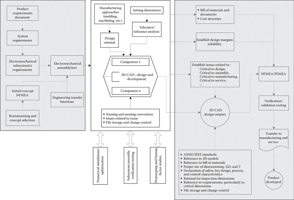
FIGURE 7.1
Product development roadmap highlighting relevant sections in Chapter 7.
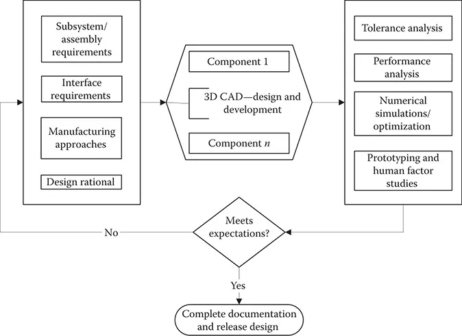
FIGURE 7.2
Steps in developing a virtual model and its verification.
Once (as shown in Figure 7.2) requirements have been decomposed into design specifications and the manufacturing approach is selected, components and assemblies may be designed using a variety of computer aided design (CAD) software. Depending on the assigned function of the component or assembly, there may be a need for tolerance and performance analysis, numerical simulation of either functions, or creating prototypes for human factor considerations and studies. Typically, this aspect of the design is an iterative process to converge to the desired configuration; and ultimately leading to release the design for manufacturing tooling. It should be noted that any requirements verification testing of assembly or subsystem requirements takes place using production tooling—and not using prototype units. If verification of requirements fails, this aspect of design must be repeated at least one more time. This broader process is demonstrated in Figure 7.4.
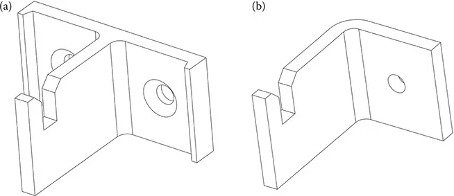
FIGURE 7.3
Component design and manufacturing interdependence example. (a) This design is suited for injection molding or machining and (b) this design is suited for stamping and sheet metal fabrication.
The process as represented in Figure 7.2 or Figure 7.4 is somewhat deceptive—or should I say oversimplified. It correctly suggests that the design team begins by decomposing assembly (or subsystem) requirements and develops design specifications. The reality is that to develop a comprehensive set of specifications, requirements, and inputs from other functions within R&D as well as from a variety of organizations outside of R&D should be taken into account and incorporated. In some organizations, the outcome of these activities and the decisions made as applicable to manufacture and service of the end product are documented in a Device Master Record document. The outcome and decisions concerning interfacing various functional inputs from within R&D are documented in a set of Interface Documents.
As shown in Figure 7.5 (and in no particular order), organizations that communicate design intent with R&D and their category of inputs are listed below:
1. Marketing as well as compliance (including regulatory) teams are labeling stakeholders. Labeling refers to any markings on the product (or shipped along with it) that communicates a message or a series of messages. An example of a label is a decal that provides information required by a regulatory body such as UL (Underwriters Laboratories), CE (Conformité Européenne, or European Conformity), or TUV (Technischer Überwachungsverein, or Technical Inspection Association). Another form of labeling is any marketing decal such as the product brand that may be printed or otherwise placed on the product. Product and shipping containers and any manuals also fall within this category. Often, the marketing team designs these documents; however, these designs are treated, maintained, and controlled as any other component design document.
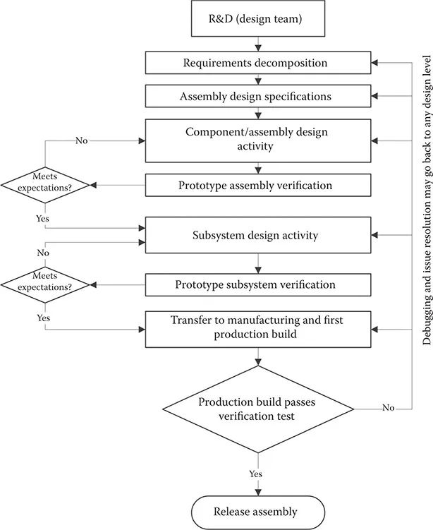
FIGURE 7.4
Steps in developing a model including its production build and verification.
2. The business team is focused on the financial aspect of the products and its impact on the so-called bottom line. Hence, one of the major and early requirements for any product is its projected cost of manufacture. This cost requirement should be properly cascaded to each subsystem and ultimately to each component. This factor influences the choice of manufacturing and production to a large extent. Associated with this cost sensitivity are influencers such as reliability. Clearly, the higher the product reliability, the lower the service and warranty costs. In addition to reliability, risk also plays an important role. No product is without risk; it so happens that some products have higher risks than others. It is the responsibility of the design team to identify risk factors and develop a risk benefit analysis of the product and identify safety-related components within the design.
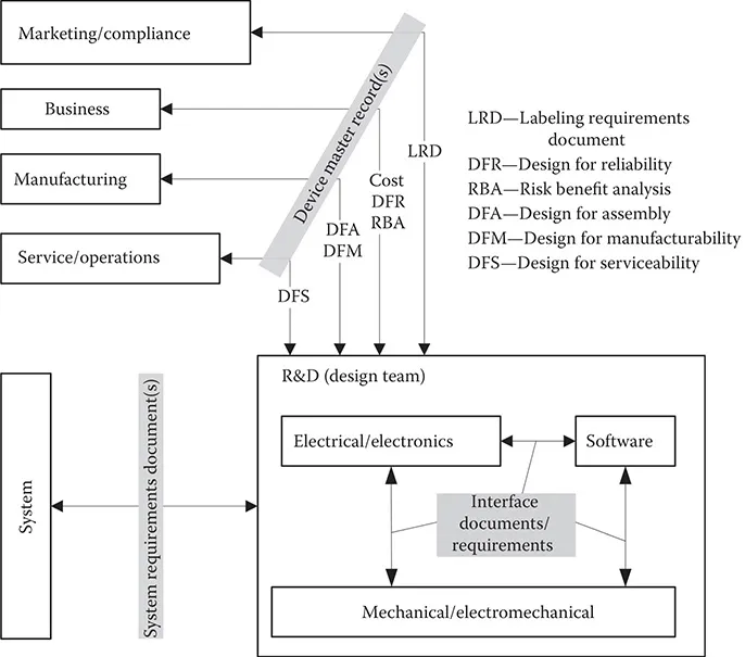
FIGURE 7.5
Interaction of cross-functional team and their influence on design.
3. Manufacturing team provides input and feedback on design for assembly (DFA) and design for manufacturability (DFM) concerns. Should the rules of DFA and DFM be properly followed, the overall cost of the product—both direct and indirect—will be lowered and optimized. However, while R&D receives information and input on DFA and DFM, it provides leadership and guidelines on what appropriate manufacturing approaches should be selected; and works closely with manufacturing to establish needed process and sets needed factors so that manufactured components meet design intent. An example of this R&D input is in injection molding components. Often, by reducing mold hold-time and pressure, an injection molding operation can save the cost of fabricating components; however, the price to be paid for this saving is higher part-to-part variability. R&D and manufacturing should partner to identify optimum process conditions that meet both design intent and manufacturing goals. Once identified, these process parameters should be captured in a related device master record.
4. Finally, the service team has a stake in the design process as well. They bring to table their expertise and know-how in service to arrange assemblies so that the service process is straightforward and time is not wasted to open the product and replace failed components. Similarly, R&D works with the service organization to provide effective diagnosis tools and codes such that a service personnel can easily and effectively identify a faulty component. As an example, many of the new computers may be considered. Once a malfunction is experienced, these newer units are equipped with a diagnosis software that may be executed at the startup of the computer. The system conducts a test of various critical components (such as memory, hard drive, or display) and reports if any issues are observed. Another example is an engine electronics module that is installed on many of the newer model automobiles. To identify any malfunctions, the mechanic attaches a diagnosis device to this module and within a short period of time, the issue is identified and located.
In addition to the showing the interrelationships between R&D’s design team and other stakeholders, Figure 7.5 points to the interrelationships between various functions within R&D. This inter-functional communication and collaboration is important even at some mundane levels. For instance, printed circuit board assemblies (PCBAs) typically designed by the electronics teams have to be mounted in enclosures designed typically by mechanical engineers. The simplest issue is placement of mounting holes and their size; who gets to dictate where these holes should...
Table of contents
- Cover
- Half Title
- Title Page
- Copyright Page
- Table of Contents
- Preface
- Acknowledgements
- Author
- Section I Front End: Product Development Lifecycle Management and Roadmap
- Section II Requirements and Their Cascade
- Section III The Nuts and Bolts of the Design
- Section IV Preparation for Product Launch
- Section V Sustaining a Marketed Product
- Section VI Best Practices and Guidelines
- References
- Index
Frequently asked questions
Yes, you can cancel anytime from the Subscription tab in your account settings on the Perlego website. Your subscription will stay active until the end of your current billing period. Learn how to cancel your subscription
No, books cannot be downloaded as external files, such as PDFs, for use outside of Perlego. However, you can download books within the Perlego app for offline reading on mobile or tablet. Learn how to download books offline
Perlego offers two plans: Essential and Complete
- Essential is ideal for learners and professionals who enjoy exploring a wide range of subjects. Access the Essential Library with 800,000+ trusted titles and best-sellers across business, personal growth, and the humanities. Includes unlimited reading time and Standard Read Aloud voice.
- Complete: Perfect for advanced learners and researchers needing full, unrestricted access. Unlock 1.5M+ books across hundreds of subjects, including academic and specialized titles. The Complete Plan also includes advanced features like Premium Read Aloud and Research Assistant.
We are an online textbook subscription service, where you can get access to an entire online library for less than the price of a single book per month. With over 1.5 million books across 990+ topics, we’ve got you covered! Learn about our mission
Look out for the read-aloud symbol on your next book to see if you can listen to it. The read-aloud tool reads text aloud for you, highlighting the text as it is being read. You can pause it, speed it up and slow it down. Learn more about Read Aloud
Yes! You can use the Perlego app on both iOS and Android devices to read anytime, anywhere — even offline. Perfect for commutes or when you’re on the go.
Please note we cannot support devices running on iOS 13 and Android 7 or earlier. Learn more about using the app
Please note we cannot support devices running on iOS 13 and Android 7 or earlier. Learn more about using the app
Yes, you can access Design of Electromechanical Products by Ali Jamnia in PDF and/or ePUB format, as well as other popular books in Business & Industrial Design. We have over 1.5 million books available in our catalogue for you to explore.