A basal reinforced piled embankment consists of a reinforced embankment on a pile foundation. The reinforcement consists of one or more horizontal layers of geosynthetic reinforcement installed at the base of the embankment.
A basal reinforced piled embankment can be used for the construction of a road or a railway when a traditional construction method would require too much construction time, affect vulnerable objects nearby or give too much residual settlement, making frequent maintenance necessary.
This publication is a guideline (CUR226) for the design of basal reinforced piled embankments. The guideline covers the following subjects: a survey of the requirements and the basic principles for the structure as a whole; some instructions for the pile foundation and the pile caps; design rules for the embankment with the basal geosynthetic reinforcement; extensive calculation examples; finite element calculations; construction details and management and maintenance of the piled embankment. The guideline includes many practical tips. The design guideline is based on state-of-the-art Dutch research, which was conducted in cooperation with many researchers from different countries.
eBook - ePub
Design Guideline Basal Reinforced Piled Embankments
- 156 pages
- English
- ePUB (mobile friendly)
- Available on iOS & Android
eBook - ePub
Design Guideline Basal Reinforced Piled Embankments
About this book
Trusted by 375,005 students
Access to over 1.5 million titles for a fair monthly price.
Study more efficiently using our study tools.
Information
Subtopic
Ingeniería civil1
Introduction
1.1 General
Worldwide, more and more basal reinforced piled embankments are being constructed for transport infrastructure. A basal reinforced piled embankment (Fig.1.1, Fig.1.2) consists of a reinforced embankment on a pile foundation. The reinforcement consists of one or more horizontal layers of geosynthetic reinforcement (GR) installed at the base of the embankment. In use, these structures exhibit little or no residual settlement.
The force transfer in the reinforced embankment is determined by arching. This is the phenomenon where loads are transferred preferentially to the stiffer elements in the ground, in this case the piles.
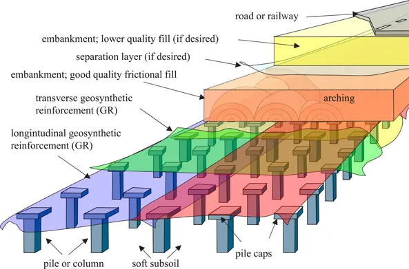
Fig. 1.1
A basal reinforced piled embankment
The pile caps are preferably positioned with their tops above the groundwater level.
All possible pile systems may be used for piled embankments, providing that the difference in stiffness between the piles and the surrounding soil is sufficiently great; see Table 4.2, boundary condition 8. Important points in the structural design are the calculation of the piles’ bearing capacity, for which the regulations in force for the design of piles are used, and the dimensioning calculation for the geosynthetic reinforcement itself.
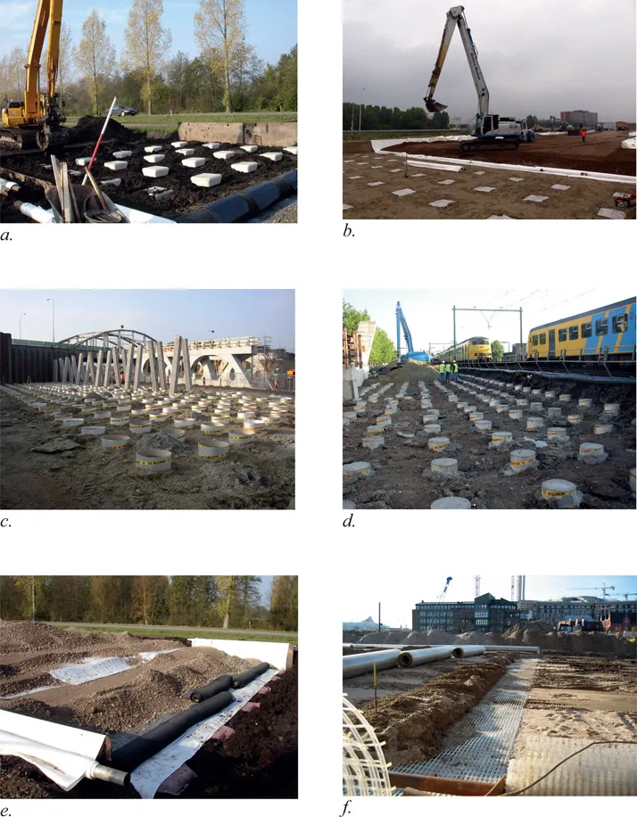
Fig.1.2 Basal reinforced piled embankments under construction. (a) Krimpenerwaard N210 (Ballast Nedam, Huesker, Fugro, Movares), (b) A-15 MAVA project, source: Royal TenCate, contractor: A-Lanes (c) Piled embankment for an abutment necessary for the widening of the A2 near Beesd, the Netherlands (Voorbij Funderingstechniek, Heijmans, CRUX Engineering, Huesker and Deltares), (d) Houten railway (Movares, de Bataafse Alliantie, (ProRail, Mobilis, CFE en KWS Infra), Huesker, Voorbij Funderingstechniek, CRUX Engineering and Deltares), (e) Krimpenerwaard N210 (Ballast Nedam, Huesker, Fugro, Movares), (f) Hamburg (Naue).
Figure published before in van Eekelen (2015), [23].
Figure published before in van Eekelen (2015), [23].
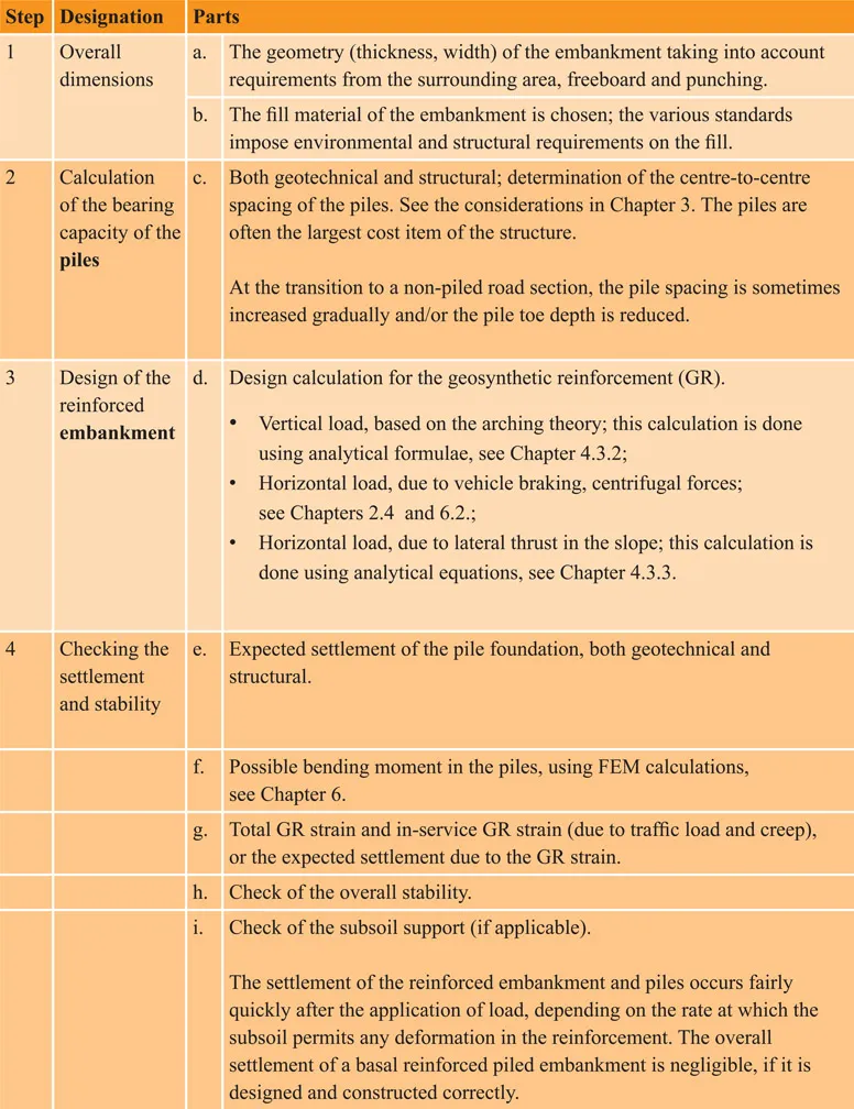
The design process for a basal reinforced piled embankment proceeds as indicated in Table 1.1. The steps 1 to 3 may be seen as the preliminary design. In these steps, the pile arrangement including pile type and GR strength are determined. Step 4 may be seen as the final design, in which additional calculations are done to determine for example bending moments in the piles, with the help of numerical calculations.
The following are considered in this publication:
- requirements for the reinforced embankment;
- requirements for the piles and pile caps and recommendations for pile and pile cap design;
- design of the reinforced embankment, including calculation examples;
- evaluation of pile moments with numerical calculations (finite element method, FEM);
- transition zones;
- construction and maintenance of the piled embankment.
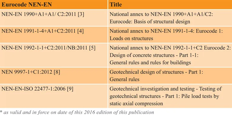
1.2 Eurocode
This 2016 publication update has been brought into conformity with the requirements of the European Eurocode. Table 1.2 gives an overview of the Eurocodes applied.
The European standards mainly concern the structural design of buildings. The requirements specified in them do not always apply to other civil engineering structures, such as embankments, bridges and viaducts.
2
Requirements and initial details of reinforced embankments
2.1 Introduction
The client’s principal requirements for the construction of a piled embankment concern:
- deformations / differential deformations;
- external loads;
- reliability class;
- service life / need for maintenance;
- limitations in use and effect on immediate environment.
These requirements are covered in this chapter.
This chapter presents additional principles and details concerning:guideline.
- pile location tolerance;
- support of the geosynthetic reinforcement by the subsoil;
- surface water;
- applicability of this design.
Chapter 3 gives principles and details concerning piles and pile caps.
In a piled embankment, the vertical load is distributed over the piles, geosynthetic reinforcement and subsoil as follows (see Fig. 2.1):
- the load part A (‘arching A’) that goes directly to the piles via the arching effect;
- the load part B that goes to the piles via the geosynthetic reinforcement;
- the load part C that is carried by the subsoil between the piles.
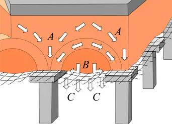
Fig. 2.1 Division of load into three parts (kN/pile): A: directly to the piles, B: via geosynthetic reinforcement to the piles, C: to the subsoil between the piles.
2.2 Deformations, settlements and differential settlements
Table 2.1 gives a summary of the current requirements on residual and differential settlements in the Netherlands. These requirements are based on a structure not founded on piles (traditional road foundation).
Table of contents
- Cover
- Title
- Copyright
- CONTENTS
- Preface
- Summary
- Nomenclature
- Chapter 1 Introduction
- Chapter 2 Requirements and initial details of reinforced embankments
- Chapter 3 Requirements and initial details for the piles and pile caps
- Chapter 4 Design of the reinforced embankment
- Chapter 5 Calculation examples for the design of reinforced embankments
- Chapter 6 Numerical modelling
- Chapter 7 Transition zones
- Chapter 8 Construction details
- Chapter 9 Management and maintenance
- Appendix A Traffic load tables
- References
Frequently asked questions
Yes, you can cancel anytime from the Subscription tab in your account settings on the Perlego website. Your subscription will stay active until the end of your current billing period. Learn how to cancel your subscription
No, books cannot be downloaded as external files, such as PDFs, for use outside of Perlego. However, you can download books within the Perlego app for offline reading on mobile or tablet. Learn how to download books offline
We are an online textbook subscription service, where you can get access to an entire online library for less than the price of a single book per month. With over 1.5 million books across 990+ topics, we’ve got you covered! Learn about our mission
Look out for the read-aloud symbol on your next book to see if you can listen to it. The read-aloud tool reads text aloud for you, highlighting the text as it is being read. You can pause it, speed it up and slow it down. Learn more about Read Aloud
Yes! You can use the Perlego app on both iOS and Android devices to read anytime, anywhere — even offline. Perfect for commutes or when you’re on the go.
Please note we cannot support devices running on iOS 13 and Android 7 or earlier. Learn more about using the app
Please note we cannot support devices running on iOS 13 and Android 7 or earlier. Learn more about using the app
Yes, you can access Design Guideline Basal Reinforced Piled Embankments by Suzanne J.M. Eekelen, Marijn H.A. Brugman, Suzanne J.M. van Eekelen,Marijn H.A. Brugman,Suzanne J.M. Eekelen, Suzanne J.M. van Eekelen, Marijn H.A. Brugman in PDF and/or ePUB format, as well as other popular books in Tecnología e ingeniería & Ingeniería civil. We have over 1.5 million books available in our catalogue for you to explore.