From the 1830s to today, the railroad industry has developed myriad complex mechanisms to help keep North America's railroad rights-of-ways safe, efficient, and relatively accident-free. In this paperback rerelease of the successful 2003 title, the otherwise-arcane world of railroad signaling is explained in concise language and brought to life with nearly 200 fantastic photographs that depict signaling history and all aspects of modern operations. Author and photographer Brian Solomon brings his wealth of knowledge and photographic talent to a subject that has not often been tackled in book form, yet is integral to the American railroad experience.
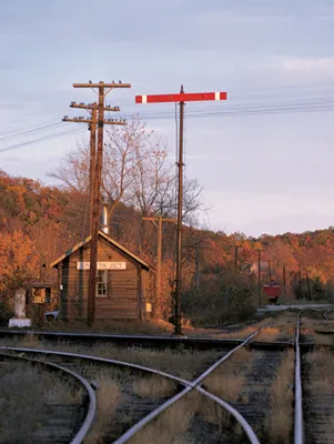
Lightly used crossings were sometimes protected by simple “tiltboard” signals. Sparta Junction, New Jersey, photographed in October 1963, was the crossing of the Lehigh and Hudson River and the New York, Susquehanna & Western. Richard Jay Solomon
EARLY HISTORY
The earliest railways had little need for complex signaling, because there were relatively few trains, and these were lightweight and traveled at slow speeds. As a result, possibilities for collisions were few, and the potential for damage was relatively low.
AS THE FREQUENCY, weight, and speed of trains increased, the potential for dangerous collisions became a problem. Early railways ran trains using a strict schedule and clear rules for operation. Timetable and rulebook operation worked well most of the time. It must be understood that in the 1820s and 1830s, before the telegraph or telephone was invented, there was no simple method for communicating the location of trains. Once a train left the station, it was out of reach. The only way to run a railway was strictly by the rules. Double-track had the advantage of increasing capacity while minimizing the potential for head-on collisions.
The Liverpool and Manchester was perhaps the first company to use a signal system. According to Richard Blythe, author of Danger Ahead, the Liverpool and Manchester positioned railway policemen along its line. Among their duties were to keep people off the tracks and indicate to passing trains the condition of the line ahead, using arm signals. An outstretched arm indicated the line was clear, while arms at the side indicated a problem. In addition, they raised a red flag when a train had paused for a station stop.
Blythe indicates that elements of Liverpool and Manchester’s signaling were derived from marine practice, including displaying a revolving lamp at the back of a train at night. The lamp featured red and blue lenses. By 1834, the Liverpool and Manchester is believed to have initiated the use of fixed signals, consisting of a post with an iron bar that could be rotated to display a red flag. If the flag was perpendicular to the rail, it indicated “danger,” but if it was parallel to the track, the line was assumed to be “clear.” Other early railways adopted similar fixed signals that used rotating paddles and boards.
The first use of fixed signals in the United States is credited to the Newcastle and Frenchtown Railroad, a 17-mile line that connected its namesake cities in Delaware and Maryland, respectively. According to Brignano and McCullough in The Search for Safety (a book on signals put out by American signal manufacturer Union Switch & Signal), the line erected a network of masts at stations along the line about three miles apart.
Initially, black and white flags were hoisted up the masts, but these proved ineffective, and the railway subsequently used balls (sometimes described as baskets that resembled balls). If a white ball was raised, the train was on time. A black ball raised meant that the train had left late. When the train had departed, the ball was lowered halfway down the mast. Unlike modern signals, these balls simply indicated a train’s progress and do not appear to have actually governed the movement of trains on the line. As with all early signals, they were operated manually.
In Britain, Isambard K. Brunel’s famous Great Western Railway, known for its 7-foot gauge tracks (technically, 7 feet, 1/4 inch between the rails), was another early user of the ball signal. In his book Red for Danger, L. T. C. Rolt explains that a ball signal was used at Reading to indicate when the station was clear. Rolt reproduces the railway’s March 1840 regulation which reads, “A Signal Ball will be seen at the entrance to Reading station when the Line is right for the train to go in. If the Ball is not visible the Train must not pass it.”
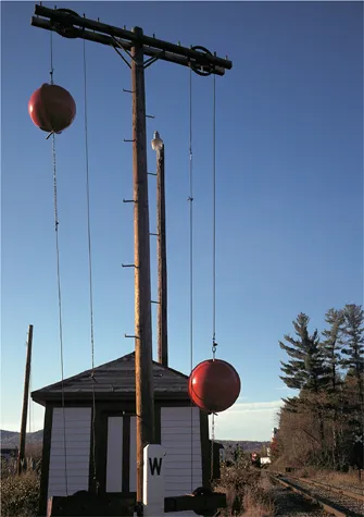
One of the earliest railroad signals was a ball on a line. This type of signal was later used at stations and gradelevel railroad crossings. The last such signal to be in regular service is at Whitefield, New Hampshire, where the former Boston & Maine crossed the Maine Central Mountain Division. Brian Solomon
In America, ball signals were typically equipped with lanterns for night indications. In later years, the balls were made from sectional copper rings and were typically painted either red or black. The ball (and lanterns) would be hoisted into position using a rope-and-pulley mechanism similar to that employed on a common clothesline but arranged vertically, parallel to the supporting mast.
Ball signals were used at stations to give trains permission to depart, and also at gradelevel crossings with other railway lines, sometimes described as “diamond crossings,” to indicate which train had the right to cross. With the simplest indications, a raised ball indicated proceed, and a lowered ball indicated stop. At locations featuring complex junctions, ball signals could be used to display more complex indications by hoisting multiple balls.
Boston & Maine Railroad Time Table No. 41, effective June 21, 1946, describes the indications of its ball signals: “Each engineman approaching the crossing will bring his engine to a stop at some point within one thousand (1,000) feet from the crossing. If the signal is right, he may then proceed.”
At White River Junction, Vermont, which had a complicated four-way junction involving a diamond crossing with Central Vermont Railway, the rules were more complicated:
One ball or one red light will allow trains from Central Vermont Ry. (Northern Division) or movements from the west to cross.
Two balls or two red lights will allow trains from the Concord-White River Jct. Main Line (N.H. Division) or movements from the east to cross, but switching may be done over crossing, east and west on two balls or two red lights.
Three balls or three red lights will allow trains from the Berlin-White River Jct. Line (N.H. Division), or movements from north to cross, but switching may be done over crossing north or south on three balls or three red lights.
Four balls or four red lights will allow trains from Central Vermont Ry. (Southern Division) or movements from the south to cross.
When no signal is displayed all trains or movements approaching the diamond must stop. Any movement over diamond when no signal is displayed will be made only on the authority of the signalman.
Although other types of signaling hardware superseded the ball signal, the ball’s legacy lives on. Ball signals such as those described above were common at level railway crossings in northern New England until the end of the steam era. Most were replaced by the mid-1960s, but the lone signal at Whitefield, New Hampshire, has survived into modern times. The use of ball signals gave way to the term “highball,” which meant proceed, and in casual speech, railroaders will still use “highball” when it’s time to leave the station. Another derivation of the word was used to describe a locomotive engineer who ran fast.
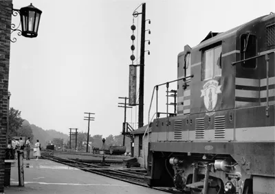
Boston & Maine used a multiple-ball signal at its diamond crossing at White River Junction, Vermont. The number of balls (or lights) displayed authorized movements across the diamond in different directions. “Four balls,” as displayed here, authorizes a movement from the Central Vermont Railway or from the south to cross. On July 27, 1957, Boston & Maine GP7 1559 is heading northward toward Woodsville and Berlin, New Hampshire. Jim Shaughnessy
BIRTH OF THE SEMAPHORE
Ships had long used systems of visual semaphore signals to communicate information. In 1841, Charles Hutton Gregory adapted a fixed semaphore for use on the London and Croydon Railway. This is often considered the first use of a fixed semaphore on a railway line and is an antecedent to most modern signaling. By the late 1840s, several prominent British railways had adopted semaphores for use on their lines. These were three-position lower-quadrant semaphores.
A semaphore is described by the number of positions its blade displays and the positions the blade occupies. With a lower-quadrant semaphore, the blade is lowered from the horizontal, which is considered the most restrictive position. A three-position semaphore’s most favorable position is the vertical. A midway position, usually at about the 45-degree mark, gives an intermediate cautionary aspect.
Upper-quadrant semaphores were developed much later and feature the blade raised from a horizontal position to indicate less restrictive aspects. On typical early three-position lower-quadrant semaphores used in Britain, the blade actually lowered into a slot in the mast to indicate “proceed.”
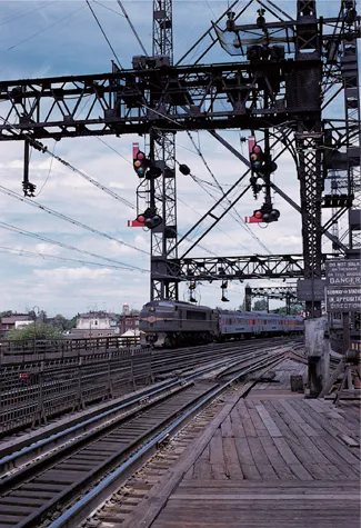
In June 1960, a New Haven Railroad EP-4 electric leads a New York–bound passenger train. The New Haven used left-handed upper-quadrant semaphores, contrary to standard practice. These short-arm semaphores were installed at Bridgeport, Connecticut, in 1912 to replace Hall disc signals. In electrified territory, New Haven’s semaphores were powered by alternating current and used high-intensity electric lamps designed to be dimmed at night. Richard Jay Solomon
These views of a Union Switch & Signal Style-S upper-quadrant semaphore on the former Erie Railroad at Tioga, New York, show the signal’s three aspects, from least restrictive to most restrictive: “clear,” “approach,” and “stop and proceed.” The Erie followed the American Association of Railroads’ standard recommended practice, using pointed-end yellow blades with a black chevron for intermediate automatic block semaphores. This signal was fitted with a number plate, needed to qualify a permissive signal. Brian Solomon
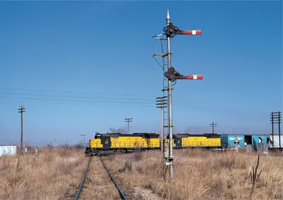
On January 24, 1981, Chicago & North Western train No. 391, led by a pair of Electro-Motive SD45s, crossed Milwaukee Road’s Moline-to-Savanna, Illinois, line at East Clinton. At that time, this crossing was still protected by electrically operated semaphores. Many lines used a squared-off blade colored red with a white stripe to indicate a home signal. Such a signal indicated an absolute “stop” when displayed in the horizontal position, as shown here. John Leopard
Until the early years of the twentieth century, the colors used to display fundamental signal aspects at night were different from what they are today. In Britain, typical signals used red for “stop”—a color that has retained its indication—but a green light indicated “caution,” while a white light was used for the “clear” indication. So a “clear” aspect indicated proceed. It is not known whether the term “a clear signal” originated because of its use of a white light or because it implied that the track ahead was unoccupied. Perhaps the dual meaning of the word was just a convenient coincidence. In any case, the use of a white light for “clear” made good sense in the early days.
Since red, green, and white were the most common colors used for night signals in Britain, the practice there inspired similar practice in the United States. However, prior to the establishment of signaling standards, every railway had its own rules, with numerous variations between different carriers’ interpretations of specific aspects and their corresponding indications.
In Britain, semaphores were erected on tall masts, so the blade could be clearly seen against the sky. A fixed semaphore had advantages: a locomotive engineer knew exactly where to look for the signal, and it could be made much taller than a man, so it could be seen more clearly from a greater distance.
In the early years the masts were made of wood, but later, iron masts were favored. Initially, signalmen manually operated the signals from the base. Since the natural weight of the signal would cause it drop into the clear position, counterweights were introduced for failsafe operation. Counterweights would force the blade into the horizontal position in case of a human failure or technical problem. Later semaphores were adapted for remote mechanical operation and, much later, for electric operation.
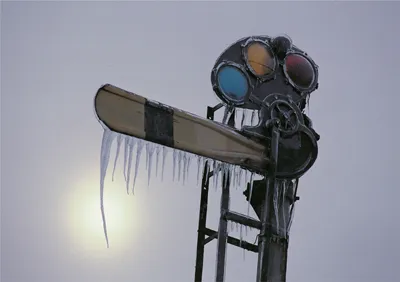
A train order signal did not provide track authority but indicated when a train should stop to collect train orders. Railroads used many styles of train order signals, which were typically located at passenger stations or towers. This one was photographed after a winter storm at Morris, Illinois, along the Rock Island. Steve Smedley
In the latter half of the nineteenth century, no instrument of technology was considered so utilitarian as to be undeserving of proper decor. The style of semaphores evolved to incorporate Victorian-era ornamentation. Styles of the blades and masts were refined. The masts were topped with ornate finials, giving the signals a touch of class while offering protection from birds that might be inclined to rest on top of them and foul the blades.
In early British practice, semaphores provided warnings by time interval systems. A signalman would display his signal in the clear position until a train passed, then railway rules instructed him to keep it in the stop position for a specific length of time. If another train came along, it was required to wait until the interval had passed. In some situations, after a length of time, the signalman could lower the semaphore to display a “caution,” to allow a train to proceed at reduced speed. Railway rules varied on whether signals should be normally kept in the “stop” position or the “clear” position.
The use of three-position lower-quadrant-style semaphores with slotted masts was once com...
Table of contents
Cover
Title Page
Contents
Acknowledgments
Introduction
1: Early History
2: Later History
3: Manual Block
4: Towers and Interlocking
5: Automatic Block
6: Centralized Traffic Control
7: Train Control and Cab Signaling
8: Grade Crossing Signals
Glossary
Bibliography
Index
Copyright Page
Frequently asked questions
Yes, you can cancel anytime from the Subscription tab in your account settings on the Perlego website. Your subscription will stay active until the end of your current billing period. Learn how to cancel your subscription
No, books cannot be downloaded as external files, such as PDFs, for use outside of Perlego. However, you can download books within the Perlego app for offline reading on mobile or tablet. Learn how to download books offline
Perlego offers two plans: Essential and Complete
Essential is ideal for learners and professionals who enjoy exploring a wide range of subjects. Access the Essential Library with 800,000+ trusted titles and best-sellers across business, personal growth, and the humanities. Includes unlimited reading time and Standard Read Aloud voice.
Complete: Perfect for advanced learners and researchers needing full, unrestricted access. Unlock 1.4M+ books across hundreds of subjects, including academic and specialized titles. The Complete Plan also includes advanced features like Premium Read Aloud and Research Assistant.
Both plans are available with monthly, semester, or annual billing cycles.
We are an online textbook subscription service, where you can get access to an entire online library for less than the price of a single book per month. With over 1 million books across 990+ topics, we’ve got you covered! Learn about our mission
Look out for the read-aloud symbol on your next book to see if you can listen to it. The read-aloud tool reads text aloud for you, highlighting the text as it is being read. You can pause it, speed it up and slow it down. Learn more about Read Aloud
Yes! You can use the Perlego app on both iOS and Android devices to read anytime, anywhere — even offline. Perfect for commutes or when you’re on the go. Please note we cannot support devices running on iOS 13 and Android 7 or earlier. Learn more about using the app
Yes, you can access Railroad Signaling by Brian Solomon in PDF and/or ePUB format, as well as other popular books in Technology & Engineering & Rail Transportation. We have over one million books available in our catalogue for you to explore.