- 533 pages
- English
- ePUB (mobile friendly)
- Available on iOS & Android
eBook - ePub
About this book
Parallel structures are more effective than serial ones for industrial automation applications that require high precision and stiffness, or a high load capacity relative to robot weight. Although many industrial applications have adopted parallel structures for their design, few textbooks introduce the analysis of such robots in terms of dynamics
Tools to learn more effectively

Saving Books

Keyword Search

Annotating Text

Listen to it instead
Information
1

Introduction

Robots are very important assets for today’s industry. The use of robots is vital in industrial automation to preserve the quantity and quality of production while introducing flexibility in the manufacturing line. The ever-increasing necessity to introduce new product styles, improve the product quality, and reduce the manufacturing costs has resulted in greater adoption of robotic equipment in various industries. At first, automobile manufacturing companies used robots in their production lines. However, in recent years, other industrial units that produce home appliances, food and pharmaceutical materials, and so on have adopted robotic systems in their production lines. A major reason for the growth in the use of industrial robots in different production lines is their significantly declining cost. In recent years, robot prices have significantly dropped while human labor costs are increasing. Also, robots are becoming more effective, faster, smarter, more accurate, and more flexible.
Industrial robots usually have an articulated structure. In these robotic manipulators, a series of links are connected in order to provide a large workspace. The motion of the robot is controlled through the individual actuators that manipulate the individual motion of each link. Although in such structures, design objectives such as a large workspace and flexibility can be well satisfied, the accuracy of the robot end effector is significantly threatened by its serial structure. For applications in which high precision and stiffness are required or a relatively high load capacity per robot weight is needed, parallel structures are the absolute alternative. Many books have focused on the theoretical and technological advancements of serial robots [5,31,163,168]. However, very few have covered the topics on the analysis, design, and control of parallel robots [105,133]. This book is intended to provide some analysis and design tools for the increasing number of engineers and researchers interested in the design and implementation of parallel robots in industries.
1.1 What Is a Robot?
A robot is a mechanical or virtual artificial agent, usually an electromechanical system, which, by its appearance or movements, conveys the sense that it has intent or agency of its own. While there are still controversies about which machines qualify as robots, a typical robot will have several, although not necessarily all, of the following properties:
• It is not natural and has been artificially created
• Can sense its environment
• Can manipulate things in its environment
• Has some degree of intelligence
• Is programmable
• Can move with one or more axes of motion
• Appears to have intent or agency
The last property, the appearance of agency, is important when people are considering whether to call a machine a robot. In general, the more a machine has the appearance of agency, the more it is considered a robot. There is no one definition of robot that satisfies everyone, and many people have written their own. For example, the international standard ISO 8373 defines a robot as
An automatically controlled, reprogrammable, multipurpose, manipulator, programmable in three or more axes, which may be either fixed in place or mobile for use in industrial automation applications.
Joseph Engelberger, a pioneer of industrial robotics [44], once remarked:
I can’t define a robot, but I know it when I see one.
The Cambridge Advanced Learner’s Dictionary defines a robot as
A machine used to perform jobs automatically, which is controlled by a computer.
The Robotics Institute of America used the following definition for a robot:
A robot is a re-programmable multi-functional manipulator designed to move materials, parts, tools, or specialized devices, through variable programmed motions for the performance of a variety of tasks.
This definition includes mechanical manipulators, numerical controlled (NC) machines, walking machines, and humanoids of science fictions. Building a humanoid capable of doing what a human being can do is an ancient dream of humankind, and technologies developments to build machines and mechanisms that can perform like humans may all be seen in the field of robotics research. Hence, robotics is a multidisciplinary engineering field of research. In industry, however, a mechanical manipulator is usually recognized as a robot which resembles the human arm.
The word robot entered the vocabulary of English as early as in 1923. This word was first used by Karel Čapek in his book Rossam’s Universal Robots [183]. Čapek visualized a situation where a bioprocess could create human-like machines devoid of emotions and souls. However, they were very strong and obeyed, and they could be produced quickly and cheaply. Soon, all major countries wanted to equip their armies with hundreds of thousands of slave robotic soldiers, who can fight with dedication but whose loss is not painful. Eventually, the robots decided to become superior to the humans and tried to take over the world. In this story, the word robota or worker was coined.
However, the emergence of industrial robots did not occur until after the 1940s. In 1946, George Devol patented a general-purpose playback device for controlling machines using magnetic recording, and in 1954, he designed the first programmable robot and coined the term universal automation, planting the seed for the name of his future company—Unimation. In the early 1980s, several robot-producing companies emerged or joined, and the number of industrial robots used in the industries increased significantly. In the second millennium, robotics research was focused more on the technology for building humanoid robots and robotic pets.
1.2 Robot Components
A mechanism or a robotic manipulator is usually built from a number of links connected to each other and to the ground or a movable base by different types of joints. The number of degrees-of-freedom of a robot depends on the number of links and the type of joints used for the construction of the robot. In this section, the definitions of links, joints, kinematic chains, mechanisms, and machines are given, and then the concept of degrees-of-freedom is described.
The individual rigid bodies that make up a robot are called the links. In industrial robots, the rigidity of the links contributes significantly to the precision and performance of the robots, and usually in the design of links, rigidity is a vital requirement. However, in applications such as space robotics or cable-driven manipulators, due to the limitations and type of applications, special designs are adopted in which the links are constructed from flexible elements. Such robots are usually called flexible link manipulators. In this book, links are treated as rigid bodies for most of the manipulators which are analyzed in different chapters, unless stated otherwise. The assumption of the rigid bodies makes the analysis of robot manipulators much easier to understand. For cable-driven parallel manipulators, the assumption of rigid bodies for the link is applicable only when the manipulator is operated with high stiffness, and the internal tensions in the cables are relatively high. In such cases, the sagging effect of the cables are negligible, and the assumption of a rigid body for the links gives us good insight into the development of a dynamic analysis and control of such manipulators. From a kinematic point of view, a single link can be defined as an assembly of members connected to each other, such that no relative motion can occur among them. For example, two gears connected by a rigid shaft are treated as a single link.
In robots, the links are connected in pairs, and the connective element between two links is called a joint. A joint provides some physical constraints on the relative motion between the two connecting members. Owing to the required relative motion in a kinematic pair, different types of joints may be distinguished.
• A revolute joint, R, permits rotation about an axis between two paired elements as shown in Figure 1.1. Hence, a revolute joint imposes five constraints between the connecting links and provides one-degree-of-freedom.
• A prismatic joint, P, permits sliding along one axis between two paired elements as shown in Figure 1.1. Hence, a prismatic joint imposes five constraints between the connecting links and provides one-degree-of-freedom.
• A cylindrical joint, C, permits rotation about one axis, and independent translation along another axis as shown in Figure 1.2. Hence, a cylindrical joint imposes four constraints between the connecting links and provides two-degrees-of-freedom.
• A universal joint, U, permits rotation about two independent axes as shown in Figure 1.2. Hence, a universal joint imposes four constraints between the connecting links and provides two-degrees-of-freedom. A universal joint can be made from two consecutive revolute joints.
• A spherical joint, S, permits free rotation of one element with respect to another element about the center of a sphere in all the three directions as shown in Figure 1.3. No translation between the paired element is permitted. Hence, a spherical joint imposes three translational constraints between the connecting links and provides three rotational degrees-of-freedom. As illustrated in Figure 1.3, a ball-and-socket joint has the kinematic structure of a spherical joint.
• A planar joint, E, permits two translational degrees-of-freedom along a plane of contact and a rotational degrees-of-freedom about an axis normal to the plane of contact, as shown in Figure 1.4. Hence, it imposes three constraints and provides three-degrees-of-freedom.

FIGURE 1.1
Schematics of a revolute joint (a) and a prismatic joint (b). (From Mathworks Inc. Schematics of a revolute joint (left) and a prismatic joint (right), 2010. Mathworks. With permission.)
Schematics of a revolute joint (a) and a prismatic joint (b). (From Mathworks Inc. Schematics of a revolute joint (left) and a prismatic joint (right), 2010. Mathworks. With permission.)
A kinematic chain is an assembly of links that is connected by joints. When every link in a kinematic chain is connected to other links by at least two distinct paths, then it is called a closed-loop chain. On the other hand, if every link is connected to its pair by only one path, the kinematic chain is called an open-loop chain. When a mechanism consists of both closed-loop and open-loop kinematic chains, it is called a hybrid kinematic chain.
As shown in Figure 1.5, a kinematic chain is called a mechanism when one of its links is fixed to the ground, which is called the base. A machine is an assembly of one or more mechanisms along with electrical and/or hydraulic components, used to transform external energy into useful work. Although in many texts the terms mechanism and machine are used synonymously, there is a definite difference between them according to the given definitions. In other words, mechanisms are used for the transmission of motion and can be converted to machines if equipment such as digital controllers, instrumentation systems, actuators, and other accessories are incorporated into their structure to produce useful work.
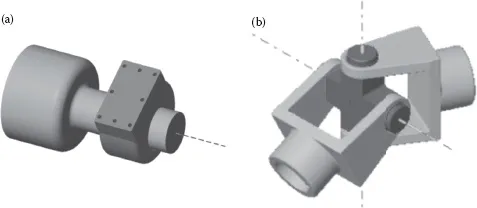
FIGURE 1.2
Schematics of a cylindrical joint (a) and a universal joint (b). (From Mathworks Inc. Schematics of a cylindrical joint (left) and a universal joint (right), 2010. Mathworks. With permission.)
Schematics of a cylindrical joint (a) and a universal joint (b). (From Mathworks Inc. Schematics of a cylindrical joint (left) and a universal joint (right), 2010. Mathworks. With permission.)

FIGURE 1.3
Schematics of a spherical joint (a) and a ball-and-socket joint (b). (From Mathworks Inc. Schematics of a spherical joint (left) and a ball-and-socket joint (right), 2010. Mathwo...
Schematics of a spherical joint (a) and a ball-and-socket joint (b). (From Mathworks Inc. Schematics of a spherical joint (left) and a ball-and-socket joint (right), 2010. Mathwo...
Table of contents
- Cover
- Title Page
- Copyright
- Contents
- Preface
- 1. Introduction
- 2. Motion Representation
- 3. Kinematics
- 4. Jacobians: Velocities and Static Forces
- 5. Dynamics
- 6. Motion Control
- 7. Force Control
- Appendix A: Linear Algebra
- Appendix B: Trajectory Planning
- Appendix C: Nonlinear Control Review
- References
- Index
Frequently asked questions
Yes, you can cancel anytime from the Subscription tab in your account settings on the Perlego website. Your subscription will stay active until the end of your current billing period. Learn how to cancel your subscription
No, books cannot be downloaded as external files, such as PDFs, for use outside of Perlego. However, you can download books within the Perlego app for offline reading on mobile or tablet. Learn how to download books offline
Perlego offers two plans: Essential and Complete
- Essential is ideal for learners and professionals who enjoy exploring a wide range of subjects. Access the Essential Library with 800,000+ trusted titles and best-sellers across business, personal growth, and the humanities. Includes unlimited reading time and Standard Read Aloud voice.
- Complete: Perfect for advanced learners and researchers needing full, unrestricted access. Unlock 1.4M+ books across hundreds of subjects, including academic and specialized titles. The Complete Plan also includes advanced features like Premium Read Aloud and Research Assistant.
We are an online textbook subscription service, where you can get access to an entire online library for less than the price of a single book per month. With over 1 million books across 990+ topics, we’ve got you covered! Learn about our mission
Look out for the read-aloud symbol on your next book to see if you can listen to it. The read-aloud tool reads text aloud for you, highlighting the text as it is being read. You can pause it, speed it up and slow it down. Learn more about Read Aloud
Yes! You can use the Perlego app on both iOS and Android devices to read anytime, anywhere — even offline. Perfect for commutes or when you’re on the go.
Please note we cannot support devices running on iOS 13 and Android 7 or earlier. Learn more about using the app
Please note we cannot support devices running on iOS 13 and Android 7 or earlier. Learn more about using the app
Yes, you can access Parallel Robots by Hamid D. Taghirad in PDF and/or ePUB format, as well as other popular books in Technology & Engineering & Electrical Engineering & Telecommunications. We have over one million books available in our catalogue for you to explore.