Classical Feedback Control with Nonlinear Multi-Loop Systems
eBook - ePub

Classical Feedback Control with Nonlinear Multi-Loop Systems

With MATLABĀ® and SimulinkĀ®, Third Edition

  1. 574 pages
  2. English
  3. ePUB (mobile friendly)
  4. Available on iOS & Android
eBook - ePub

Classical Feedback Control with Nonlinear Multi-Loop Systems

With MATLABĀ® and SimulinkĀ®, Third Edition

Book details
Book preview
Table of contents
Citations

About This Book

Classical Feedback Control with Nonlinear Multi-Loop Systems describes the design of high-performance feedback control systems, emphasizing the frequency-domain approach widely used in practical engineering. It presents design methods for high-order nonlinear single- and multi-loop controllers with efficient analog and digital implementations. Bode integrals are employed to estimate the available system performance and to determine the ideal frequency responses that maximize the disturbance rejection and feedback bandwidth. Nonlinear dynamic compensators provide global stability and improve transient responses. This book serves as a unique text for an advanced course in control system engineering, and as a valuable reference for practicing engineers competing in today's industrial environment.

Frequently asked questions

Simply head over to the account section in settings and click on ā€œCancel Subscriptionā€ - itā€™s as simple as that. After you cancel, your membership will stay active for the remainder of the time youā€™ve paid for. Learn more here.
At the moment all of our mobile-responsive ePub books are available to download via the app. Most of our PDFs are also available to download and we're working on making the final remaining ones downloadable now. Learn more here.
Both plans give you full access to the library and all of Perlegoā€™s features. The only differences are the price and subscription period: With the annual plan youā€™ll save around 30% compared to 12 months on the monthly plan.
We are an online textbook subscription service, where you can get access to an entire online library for less than the price of a single book per month. With over 1 million books across 1000+ topics, weā€™ve got you covered! Learn more here.
Look out for the read-aloud symbol on your next book to see if you can listen to it. The read-aloud tool reads text aloud for you, highlighting the text as it is being read. You can pause it, speed it up and slow it down. Learn more here.
Yes, you can access Classical Feedback Control with Nonlinear Multi-Loop Systems by Boris J. Lurie,Paul Enright in PDF and/or ePUB format, as well as other popular books in Physical Sciences & Mechanics. We have over one million books available in our catalogue for you to explore.

Information

Publisher
CRC Press
Year
2019
ISBN
9781351011839
Edition
3
Subtopic
Mechanics

1

Feedback and Sensitivity

Chapter 1 introduces the basics of feedback control. The purpose of feedback is to make the output insensitive to plant parameter variations and disturbances. Negative, positive, and large feedback are defined and discussed along with sensitivity and disturbance rejection. The notions of frequency response, the Nyquist diagram, and the Nichols chart are introduced. (The Nyquist stability criterion is presented in Chapter 3.)
Feedback control and block diagram algebra are explained at an elementary level in Appendix 1, which can be used as an introduction to this chapter. Laplace transfer functions are described in Appendix 2.

1.1 Feedback Control System

It is best to begin with an example. Figure 1.1a depicts a servomechanism regulating the elevation of an antenna. Figure 1.1b shows a block diagram for this control system made of cascaded elements, i.e., links. The capital letters stand for the signalsā€™ Laplace transforms and also for the transfer functions of the linear links.
FIGURE 1.1
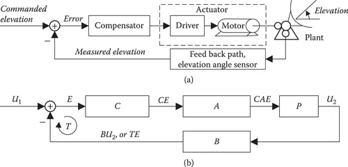
Single-loop feedback system.
There is one input command U 1, which is the commanded elevation angle, and just one output U 2, which is the actual elevation of the antenna, so the system is said to be single-input single-output (SISO). Evidently there is one feedback loop, and so the system is also referred to as single-loop.
The feedback path contains some sort of sensor for the output variable and has the transfer function B. Ideally, the measured output value BU 2 equals the commanded value U 1, and the error E = U 1 ā€“ BU 2, at the output of the summer, is zero. In practice, most of the time the error is nonzero but small.
The error is amplified by the compensator C and applied to the actuator A, in this case a motor regulator (driver) and a motor, respectively. The motor rotates the plant P, the antenna itself, which is the object of the control. The compensator, actuator, and plant make up the forward path with the transfer function CAP.
The return signal, which goes into the summer from the feedback path, is BU 2 = TE, where the product T = CAPB = BU 2/E, is called the loop transfer function or the return ratio.
The output of the summer is:
E = U 1 āˆ’ E T (1.1)
so that the error can be expressed as
E = U 1 T + 1 = U 1 F (1.2)
where F = T + 1 is the return difference. Its magnitude |F| is the feedback. It is seen that when the feedback is large, the error is small.
If the feedback path was not present, the output U 2 would simply equal the product CAPU 1, and the system would be referred to as open-loop.
Example 1.1
A servomechanism for steering a toy car (using wires) is shown in Figure 1.2. The command voltage U 1 is regulated by a joystick potentiometer. Another identical potentiometer (angle sensor) placed on the shaft of the motor produces voltage U angle proportional to the shaft rotation angle. The feedback makes the error small, so that the sensor voltage approximates the input voltage, and therefore the motor shaft angle tracks the joystick-commanded angle.
FIGURE 1.2
Joystick control of a steering mechanism.
This arrangement of a motor with an angle sensor is often called servomotor, or simply servo. Similar servos are used for animation purposes in movie production.
The system of regulating aircraft-control surfaces using joysticks and servos was termed ā€œfly by wireā€ when it was first introduced to replace bulky mechanical gears and cables. The required high reliability was achieved by using four independent parallel analog electrical circuits.
The telecommunication link between the control box and the servo can certainly also be wireless.
Example 1.2
A phase-locked loop (PLL) is shown in Figure 1.3. The plant here is a voltage-controlled oscillator (VCO).
FIGURE 1.3
Phase-locked loop.
The VCO is an ac generator whose frequency is proportional to the voltage applied ...

Table of contents

  1. Cover
  2. Half-Title
  3. Series
  4. Title
  5. Copyright
  6. Contents
  7. Preface
  8. To Instructors
  9. Authors
  10. 1 Feedback and Sensitivity
  11. 2 Feedforward, Multi-Loop, and MIMO Systems
  12. 3 Frequency Response Methods
  13. 4 Shaping the Loop Frequency Response
  14. 5 Compensator Design
  15. 6 Analog Controller Implementation
  16. 7 Linear Links and System Simulation
  17. 8 Introduction to Alternative Methods of Controller Design
  18. 9 Adaptive Systems
  19. 10 Provision of Global Stability
  20. 11 Describing Functions
  21. 12 Process Instability
  22. 13 Multiwindow Controllers
  23. 14 Nonlinear Multi-Loop Systems with Uncertainty
  24. Appendix 1: Feedback Control, Elementary Treatment
  25. Appendix 2: Frequency Responses
  26. Appendix 3: Causal Systems, Passive Systems and Positive Real Functions, and Collocated Control
  27. Appendix 4: Derivation of Bode Integrals
  28. Appendix 5: Program for Phase Calculation
  29. Appendix 6: Generic Single-Loop Feedback System
  30. Appendix 7: Effect of Feedback on Mobility
  31. Appendix 8: Regulation
  32. Appendix 9: Balanced Bridge Feedback
  33. Appendix 10: Phase-Gain Relation for Describing Functions
  34. Appendix 11: Discussions
  35. Appendix 12: Design Sequence
  36. Appendix 13: Examples
  37. Appendix 14: Bode Step Toolbox
  38. Appendix 15: Nonlinear Multi-Loop Feedback Control (Patent Application)
  39. Bibliography
  40. Notation
  41. Index