- 418 pages
- English
- ePUB (mobile friendly)
- Available on iOS & Android
eBook - ePub
Optimization of Unit Operations
About this book
This comprehensive book examines the technology and practical applications of plant multivariable envelope control. Optimize plant productivity, including air handlers, boilers, chemical reactors, chillers, clean-rooms, compressors and fans, cooling towers, heat exchangers, and pumping stations.
Béla G. Lipták speaks on Post-Oil Energy Technology on the AT&T Tech Channel.
Tools to learn more effectively

Saving Books

Keyword Search

Annotating Text

Listen to it instead
Information
Chapter 1
OPTIMIZATION OF AIRHANDLERS
Components of an Airhandler
Operating Mode Selection
Summer/Winter Mode Reevaluation
Emergency Mode
Fan Controls
Dampers as Control Elements
Temperature Controls
Special-Purpose Thermostats
Zero Energy Band Control
Gap Control and the Self-Heating Building
Supply Air Temperature Control
Humidity Controls
Outdoor Air Controls
CO2 Based Ventilation
Economizer Cycles
Optimizing Strategies
Temperature Optimization in the Winter
Temperature Optimization in the Summer
Auto-Balancing of Buildings
Start-Up Algorithm
Normal Algorithm for VAV Throttling
Optimization of Air Supply Pressure and Temperature
Elimination of Chimney Effects
Conclusions
References
THE AIRHANDLER is the basic unit operation of space conditioning. It is used to keep occupied spaces comfortable (figure 1.1) or unoccupied spaces at desired levels of temperature and humidity. In addition to supplying or removing heat and/or humidity from the conditioned space, the airhandler also provides ventilation and fresh air makeup. Depending on the type of space involved, from 75,000–300,000 Btu/yr. (19,000–76,000 Cal/yr.) are required to condition one square foot (0.092 m2) of office space. Depending on the energy sources used, this corresponds to a yearly operating cost of a few dollars per square foot of floor space.
Whereas other unit operations have benefited substantially from the advances in process control, airhandlers have not. Airhandlers today are frequently controlled the same way as they were twenty or thirty years ago. For this reason, airhandler optimization can result in much greater percentages of savings than can the optimization of any other unit operation. Optimization can cut the cost of airhandler operation in half—a savings that can seldom be achieved in any other type of unit operation.
Some of the optimization goals and strategies include the following:
- • Let the building heat itself
- • Use free cooling and/or free drying
- • Benefit from gap control or zero energy band (ZEB)
- • Eliminate chimney effect
- • Optimize start-up timing
- • Optimize air make-up (CO2)
- • Optimize supply air temperature
- • Minimize fan energy use
- • Automate the selection of operating modes
- • Minimize reheat
- • Automate balancing of air distribution
Components of an Airhandler
The purpose of heating, ventilation, and air conditioning (HVAC) controls is to provide comfort in laboratories, clean rooms, warehouses, offices, and manufacturing spaces. Supply air is the means of providing comfort in the conditioned zone. The air supplied to each zone must provide heating or cooling, raise or lower humidity, and provide air refreshment. To satisfy these requirements, it is necessary to control the temperature, humidity, and fresh air ratio in the supply air.
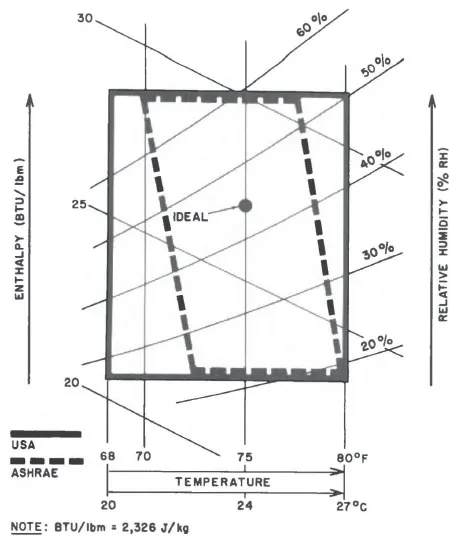
Figure 1.2 illustrates the main components of an airhandler. The term airhandler refers to the total system, including fans, heat-exchanger coils, dampers, ducts, and instruments. The system operates as follows: outside air is admitted by the outside air damper (OAD-05) and is then mixed with the return air from the return air damper (RAD-04). The resulting mixed air is filtered (F), heated (HC) or cooled (CC), and humidified (H) or dehumidified (CC) as required. The resulting supply air is then transported to the conditioned zones (groups of offices) by the variable-volume supply fan station. Variable volume means that the air flow rate generated by the fan(s) is variable.
In each zone, the variable air volume damper (VAV-23) determines the amount of air required, and the reheat coil (RHC) adjusts the air temperature as needed. The return air from the zones is transported by the variable-volume return-air fan station. If the amount of available return air exceeds the demand for it, the excess air is exhausted by the exhaust air damper (EAD-03). The conditioned spaces are typically pressurized to about 0.1″H2O (25 Pa), relative to the barometric pressure on the outside. This pressurization results in some air leakage through the walls and windows, which varies with the quality of construction. Therefore, the air balance around the system is:
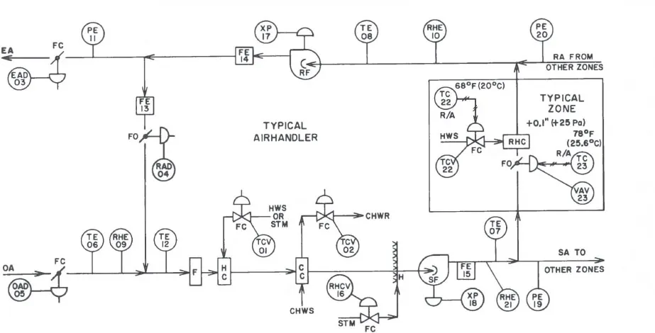
Fig. 1.2 A typical major airhandler has these components and controls. [From Lipták [8])
CC = Cooling coil
CHWR = Chilled water return
EA = Exhaust air
EAD = Exhaust air damper
F = Filter
FE = Flow element
FC = Fail closed
FO = Fail open
H = Humidifier
HC = Heating coil
HWS = Hot water supply
OA = Outside air
OAD = Outside air damper
PE = Pressure element
RA = Return air
RAD = Return air damper
RF = Return fan
RHC = Reheat coil
RHCV = Relative humidity control valve
RHE = Relative humidity element
SA = Supply air
SF = Supply fan
STM = Steam
TCV = Temperature control valve
TE = Temperature element
VAV = Variable air volume damper
XP = Positioner for fan volume control, such as a blade pitch positioner
Under “normal” operation, the airhandler operates with about 10 percent outside air. In the “purge” or “free cooling” modes, RAD is closed, OAD is fully open, and the airhandler operates with 100 percent outside air.
As can be seen, the HVAC process is rather simple. Its process material is clean air, its utility is water or steam, and its overall system behavior is slow, stable, and forgiving. For precisely these reasons, it is possible to obtain acceptable HVAC performance using inferior-quality instruments, which are configured into poorly designed loops. Yet there is an advantage in applying the state of the art of process control to the HVAC process, because it can provide a drastic reduction in operating costs, attributable to increased efficiency of operation. Some of the more efficient control concepts are described in the sections below.
Operating Mode Selection
The correct identification and timing of the various operating modes can contribute to the optimization of the building. The normal operating modes include start-up, occupied, night, and purge.
Optimizing the time of start-up will guarantee that the minimum required cost is invested in getting the building ready for occupancy. This is done by automatically calculating the amount of heat that needs to be transferred and dividing it according to the capacity of the start-up equipment. A computer-optimized control system will serve to initiate the unoccupied (night) mode of operation; it will also recognize weekends and holidays and, in general, provide a flexible means of time-of-day controls.
The purge mode is another convenient tool of optimization. Whenever the outside air is preferred to the return air, the building is automatically purged. In this way, “free cooling” can be obtained on dry summer mornings or “free heating” can be provided on warm winter afternoons. Purging is the equivalent of opening the windows in a home. In computer-optimized buildings, an added potential is to use the building structure as a means of heat (or coolant) storage. In this case, the purge mode can be automatically initiated during cold nights prior to hot summer days, thereby bringing the building temperature down and storing some free cooling in the building structure.
Summer/Winter Mode Reevaluation
Another important mode selection involves switching from summer to winter mode and vice versa. Conventional systems are switched according to the calendar, whereas optimized ones recognize that there are summerlike days in the winter and winterlike hours during summer days. Seasonal mode switching is therefore totally inadequate. Optimized building operation can be provided only by making the summer/winter selection on an enthalpy basis: if heat needs to be added, it is “winter”; if heat needs to be removed...
Table of contents
- Cover
- Half Title
- Title Page
- Copyright Page
- Dedication
- Table of Contents
- Preface
- Chapter 1 Optimization of Airhandlers
- Chapter 2 Optimization of Boilers
- Chapter 3 Optimization of Chemical Reactors
- Chapter 4 Optimization of Chillers
- Chapter 5 Optimization of Clean-Rooms
- Chapter 6 Optimization of Compressors and Fans
- Chapter 7 Optimization of Cooling Towers
- Chapter 8 Optimization of Heat Exchangers
- Chapter 9 Optimization of Pumping Stations
- Index
Frequently asked questions
Yes, you can cancel anytime from the Subscription tab in your account settings on the Perlego website. Your subscription will stay active until the end of your current billing period. Learn how to cancel your subscription
No, books cannot be downloaded as external files, such as PDFs, for use outside of Perlego. However, you can download books within the Perlego app for offline reading on mobile or tablet. Learn how to download books offline
Perlego offers two plans: Essential and Complete
- Essential is ideal for learners and professionals who enjoy exploring a wide range of subjects. Access the Essential Library with 800,000+ trusted titles and best-sellers across business, personal growth, and the humanities. Includes unlimited reading time and Standard Read Aloud voice.
- Complete: Perfect for advanced learners and researchers needing full, unrestricted access. Unlock 1.4M+ books across hundreds of subjects, including academic and specialized titles. The Complete Plan also includes advanced features like Premium Read Aloud and Research Assistant.
We are an online textbook subscription service, where you can get access to an entire online library for less than the price of a single book per month. With over 1 million books across 990+ topics, we’ve got you covered! Learn about our mission
Look out for the read-aloud symbol on your next book to see if you can listen to it. The read-aloud tool reads text aloud for you, highlighting the text as it is being read. You can pause it, speed it up and slow it down. Learn more about Read Aloud
Yes! You can use the Perlego app on both iOS and Android devices to read anytime, anywhere — even offline. Perfect for commutes or when you’re on the go.
Please note we cannot support devices running on iOS 13 and Android 7 or earlier. Learn more about using the app
Please note we cannot support devices running on iOS 13 and Android 7 or earlier. Learn more about using the app
Yes, you can access Optimization of Unit Operations by Bela G. Liptak in PDF and/or ePUB format, as well as other popular books in Technology & Engineering & Electrical Engineering & Telecommunications. We have over one million books available in our catalogue for you to explore.