![]()
Selecting Safety Integrity Levels: Introduction
The purpose of a safety instrumented system (SIS) is to reduce the risk that a process may become hazardous to a tolerable level. The SIS does this by decreasing the frequency of unwanted accidents. The amount of risk reduction that an SIS can provide is represented by its safety integrity level (SIL), which is defined as a range of probability of failure on demand. An SIS senses hazardous conditions and then takes action to move the process to a safe state, preventing an unwanted accident from occurring. The method organizations use to select SILs should be based on their risk of accident, an evaluation of the potential consequences and likelihoods of an accident, and an evaluation of the effectiveness of all relevant process safeguards. Implementing an SIS, and therefore selecting an SIL, should involve considering relevant laws, regulations, and national and international standards. In the United States, the “Process Safety Management” (PSM) section of the OSHA standard OSHA 29 CFR Part 1910.119 requires organizations to provide assurance of the mechanical integrity of all their emergency shutdown systems and safety critical controls. The “Seveso Directive” (96/82/EC) promulgates similar requirements in the European Union. In the United States, ISA—The Instrumentation, Systems, and Automation Society promulgated industry standard ANSI/ISA-84.01-1996 to promote compliance with the PSM regulation. The International Electrotechnical Commission (IEC) created a similar document, IEC 61508, which is an umbrella standard that covers numerous industries. IEC standard 61511 is the process-sector specific standard that falls under the IEC 61508 umbrella. This standard, when ratified, will be reviewed by ISA SP84 and accepted as a replacement for ANSI/ISA-84.01, possibly with some modification. The IEC standard 61511 will have a global scope.
ANSI/ISA-84.01-1996 and IEC 61508/61511 use the concept of the safety life cycle as a tool for managing the application of safety instrumented systems. As an integral part of the safety life cycle, the selection of an SIL forms the foundation of a management system that can assure safe processes. International standards for SIS design, such as ANSI/ISA-84.01-1996 and IEC 61508 and 61511, require that an SIL be selected. These standards are the basis of organizations’ efforts to comply with the local and national laws and regulations that govern processes that contain significant risks. Many “authorities having jurisdiction,” who are responsible for enforcing these laws and regulations, tend to view complying with such international standards as equivalent to complying with “good and generally recognized engineering practices” clauses.
1.1Safety Integrity Level
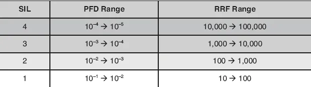
Safety integrity levels (SILs) are categories based on the probability of failure on demand (PFD) for a particular safety instrumented function (SIF). The categories of PFD range from one to three, as defined by ANSI/ISA- 84.01-1996, or one to four as defined by IEC 61508 and 61511. Table 1.1 shows the PFD ranges and associated risk reduction factor (RRF) ranges that correspond to each SIL.
Table 1.1Safety Integrity Levels and Corresponding PFD and RRF
The SIL is the key design parameter specifying the amount of risk reduction that the safety equipment is required to achieve for a particular function in question. If an SIL is not selected, the equipment cannot be properly designed because only the action is specified, not the integrity. To properly design a piece of equipment, two types of specifications are required: a specification of what the equipment does and a specification of how well the equipment performs that function. The safety integrity level addresses this second specification by indicating the minimum probability that the equipment will successfully do what it is designed to do when it is called upon to do it.
In comparing safety equipment design to the more traditional design of a control system, one could say that specifying the action of a safety instrumented function and not specifying the SIL is like specifying a control valve without specifying the flow rate (or Cv) of the valve. Although you could pick a valve without knowing the flow rate (perhaps by simply choosing the same size as the piping and selecting equal percentage trim), your selection would not be optimal. You would have no guarantee that the valve would be able to pass the proper flow rate, and you would almost be guaranteed to have selected a valve that is oversized, and thus overpriced. You could improve performance and lower capital expenditures by investing the effort required to select a piece of equipment that not only performs the proper function, but also has the required performance characteristics.
Selecting safety integrity level involves giving a numerical target upon which subsequent steps in the safety life cycle are based. Thus SIL selection offers an important guide when you are selecting equipment and making maintenance decisions. The SIL is documented along with the SIS operational requirements and logic as part of the safety requirements specification. This specification provides the foundation for all of the safety life cycle activities an organization later conducts.
IMPORTANT: The process we are referring to as SIL selection in this book has been described by many other terms, including
SIL determination and
SIL classification. We specifically chose
SIL selection because it describes the overall process most clearly.
Determination is a vague term allowing too many variations in connotation.
SIL classification implies that the process does not involve making a decision and that every situation is the same if you know its category.
Selection is the clearest and most descriptive term because it emphasizes the act of choosing the correct value based on clear criteria.
1.2Safety Instrumented Functions
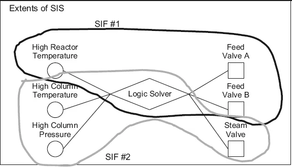
In this book, we will adopt the terminology of IEC 61511, wherein a safety instrumented function (SIF) is an action a safety instrumented system takes to bring the process or the equipment under control to a safe state. This function is a single set of actions that protects against a single specific hazard. A safety instrumented system (SIS), on the other hand, is a collection of sensors, logic solvers, and actuators that executes one or more safety instrumented functions that are implemented for a common purpose, such as a group of functions protecting the same process or implemented on the same project. Note that the term SIF often refers to the equipment that carries out the single set of actions in response to the single hazard, as well as to the particular set of actions itself. Here are some examples:
•SIF 1: High reactor temperature closes the two reactor feed valves.
•SIF 2: High column pressure or high column temperature closes a valve in the steam to the reboiler.
•SIF 3: High column pressure closes the two reactor feed valves.
The logic for all safety functions is performed in a safety PLC. This PLC would then combine with all of the equipment associated with each SIF to constitute the SIS.
Figure 1.1Safety Instrumented Functions versus Safety Instrumented Systems
You may implement one or more SIFs in a SIS, as shown in figure 1.1. ANSI/ISA-84.01-1996 uses the terms SIF and SIS in a somewhat interchangeable and confusing way. IEC 61511 makes the distinction between SIF and SIS very clear. As figure 1.1 shows, a safety function can include multiple inputs and outputs. SIF 1 is executed with two outputs, that is, the two reactor feed valves, and SIF 2 has two inputs, that is, the high pressure and high temperature measurements. It is also important to note that a multiple SIF system can include common equipment. For instance, in figure 1.1, both SIFs use the same logic solver. In instances where common equipment is used in multiple SIFs, the common equipment item should be designed to meet the SIL of the SIF that has the highest requirements.
IMPORTANT: The SIL belongs to the specific safety instrumented function (SIF), not to the entire safety instrumented system (SIS). When an equipment item is common to multiple SIFs, it should be designed to meet the highest SIL requirements of the SIF it supports.
Throughout this book, we use the word selection to describe the overall process of choosing an SIL and assignment to define the final stage of the process, in which the SIL is assigned based on the results of the analysis that led to the selection.
1.3SIL Selection and Risk
The reason an organization should use a systematic methodology, which includes layer of protection analysis, to select safety integrity level is to make the choice that best reduces risk. A good decision during this phase of the safety life cycle will ensure that the safety system specified will be cost-effective while still providing appropriate loss prevention. To make the best decision about safety integrity level, an SIS designer needs to completely understand not only the potential likelihood of an unwanted event, but also the possible consequences of that event. Viewing either of these two facets of the risk equation in isolation will yield poor results. Once the risk is known, one must determine how to reduce that risk to...