![]()
1
CREATING LIGHT
Most of what an artist needs to know about electronics is very simple. There may be a lot of little things to play with, but each component is easy to understand.
Start with the light-emitting diode, called an LED for short. You put electricity through it, and it lights up. That seems pretty simple.
Like all electronics, LEDs can seem a lot less simple if you don’t know their basic rules.
An LED has two wires coming out of it. If you connect one wire to the positive side of a battery, and the other side to the negative side of the battery, you have a 50 percent chance it will light up. If it doesn’t light up, turn the battery around and it will.
The first rule of LEDs is the diode part of the name at work: a diode only allows electricity to go through it in one direction.
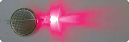
The tiny little button-cell battery in the photo above is just strong enough to light the LED. What would happen if you connected the LED to the battery in a car, or to a 9-volt battery? That would not be a good idea. At best, the LED would make a little pop sound and become a dark-emitting diode, which we will call a DED.
The second rule of LEDs: they can only handle a certain amount of electricity.
Electricity is just moving electrons. As electrons move through a conductor such as a wire or an LED, they bump into the atoms in the conductor, causing the conductor to heat up. The temperature rises, but as the temperature becomes higher than that of the surroundings, more of the heat is lost to the environment. So eventually, the LED reaches a stable temperature, where the amount of heat generated equals the amount of heat lost.
Each second, some number of electrons move through the LED. If the number of electrons per second goes up, so does the temperature. At some point, the temperature of the LED is so high that the little chip inside the LED breaks or the tiny little wires that connect to the top of the LED chip simply melt.
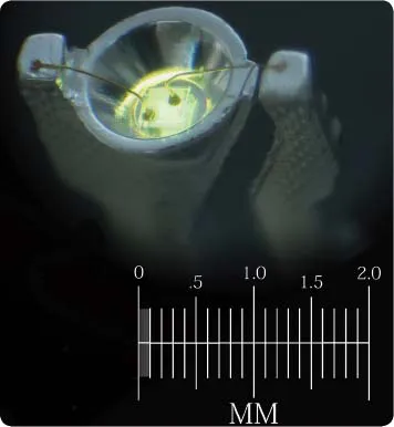
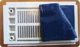
You can see two of those tiny little gold wires in the photo enlargement above. A yellow LED chip is glowing inside the small reflector cup. The entire LED is usually encased in a plastic lens, making it very difficult to see. But for this photo, I placed the glowing LED in some oil so that you could see through the plastic easily.
Just as a current of water is measured by how many gallons flow by each second, currents of electricity are measured by how many electrons flow by each second. Electrical current is measured in units called amperes.
The LED shown can handle about 0.030 amperes (30 milliamperes) before it overheats. Knowing that, you then need to make sure that no more than 30 milliamps go through the LED. You do that by adding a resistor.
A resistor is a bottleneck for electric current. A resistor can be something as simple as a narrow wire. The thinner the wire, the less electricity can go through it.
You can also make a resistor by using a wire made from something that electrons have a difficult time moving through. Carbon is such a material. It is made up of many little grains, and where the grains touch, the electrons can go from one grain to the next. However, the grains only touch in tiny spots, just like two balls can only touch in one tiny spot when put together. In this way, they restrict the flow of electrons like the thin wire does. Materials like carbon also hold on to their electrons more tightly than copper wire does, so there are fewer electrons available to move.
So you could try lighting an LED from a 9-volt battery through a resistor to keep the current below 30 milliamps. But how much resistance would you need?
A 9-volt battery pushes electrons through an LED three times harder than a 3-volt battery does. Voltage is just the pressure on the electrons. If you put more pressure on the electrons, more of them will flow through the resistor, and through the LED in each second.
To figure out how much resistance you need to add, you can measure the current in your circuit while you gradually reduce the resistance, until you get to the value you want.
I picked a few resistors almost at random to try in the circuit. Resistance is measured in ohms, and I picked two resistors with 220 ohms and one with 1,000 ohms. Resistors have color codes to tell you what values they are, and the two 220-ohm resistors have the color code red, red, brown, gold. You can memorize the resistor color codes or print them out on paper (see page 13 for more information), or you can just use a multimeter, which can measure the resistance directly.
Once you’ve chosen your resistors, you need a way to create the circuit connecting them, the battery, and the LED. The projects discussed in this book are going to use solderless breadboards a lot, since they make building such circuits much easier. A solderless breadboard has rows of holes you can poke wires into. On the edges are two rows of holes that are all electrically connected to the other holes in the same row. In the middle are numerous groups of holes in columns of five; each of the holes in a column is electrically connected to the other holes in the same column. If you put a wire into one of the five holes and a second wire into another of the same group of five, the two wires will be electrically connected.
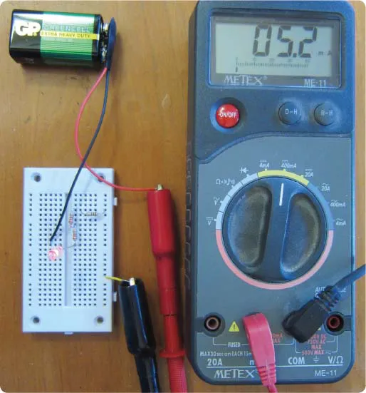
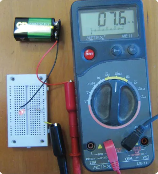
In the photo above, my three resistors are connected to a battery, an LED, and a multimeter via a solderless breadboard. The resistors are the small brown tubes at the center of the breadboard (note the color-coded stripes). The electrons come out of the battery through the black wire. They then go through the LED. From there they go through one 220-ohm resistor, then the other, then the 1,000-ohm resistor, and then (via the yellow wire) into the multimeter. Finally, they exit the meter and return to the battery. They make the full circle through all the parts and back to the battery through the red wire. This is why it is called an electric circuit.
To help you understand how solderless breadboards are constructed, the photo below shows one where I have removed the sticky tape from the back so that you can see the rows and columns of metal connectors joining all the holes. Each connector is a U-shaped bit of metal that is springy enough to open up a little when a wire is pushed into it but strong enough to hold the wire in place.
Now back to the original circuit. The meter is showing that there are only 5.2 milliamps flowing through the LED and the resistors. Since you wanted 30 milliamps, you know that you have too much resistance.
Try using just the 1,000-ohm resistor. The photo on the previous page shows the meter reads 7.6 milliamps. That is a little closer but still not the 30 milliamps you want. You want the LED to glow as brightly as it safely can.
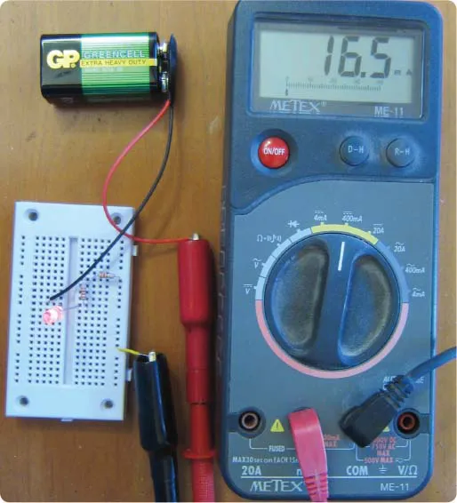
The photo above shows the circuit with just the two 220-ohm resistors (440 ohms altogether). The meter is showing 16.5 milliamps, more than half of what you are aiming for. What happens if you use just one of the 220-ohm resistors?
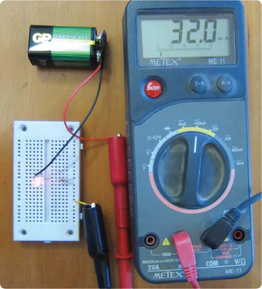
Oops! You overshot the mark … but not by a lot. You are only high by a little less than 7 percent, and the LED can handle that. No popping noises, no dark-emitting diodes. Success!
Rather than do all of that resistor swapping and guessing, wouldn’t it be nice if you could just plug in the voltage you have, and the current you want, and have a calculator figure out what resistor to use? You can, but to figure out what to enter into the calculator, you need to know a third rule about diodes.
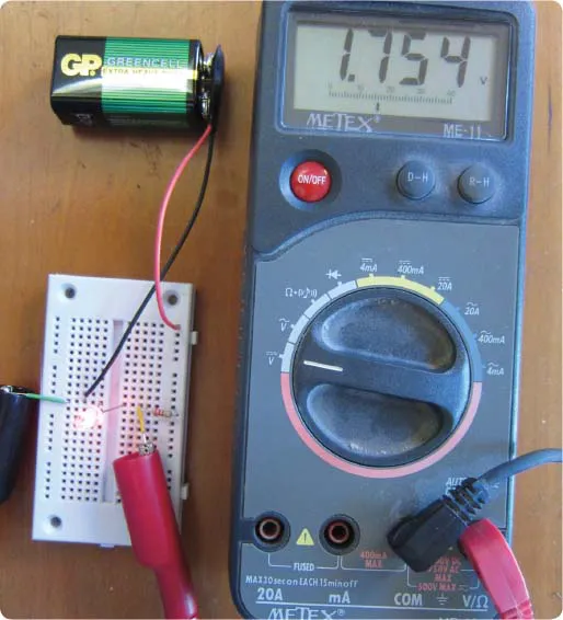
In the photo above, the meter leads are connected to the leads of the LED in the circuit. The multimeter has been switched to read volts. The meter tells you that the voltage difference between those two spots (the two legs of the diode) is 1.754 volts. Each different kind of diode has a characteristic voltage, called the forward voltage drop. For red LEDs, it is about 1.75 to 1.8 volts. For other colors, it is higher as the colors go through the spectrum. Green LEDs might...