1.1 Introduction
Carbon nanotubes (CNTs) constitute a nanostructured carbon material that consists of rolled up layers of sp2 hybridized carbon atoms forming a honeycomb lattice. After diamond, graphite and fullerenes, the one- dimensional tubular structure of CNTs isis considered the 4th allotrope of carbon (graphene is the 5 th).
For a long time the discovery of CNTs was attributed to the S. Iijima, who investigated soot formation during the production of fullerenes via arc discharge and observed the presence of “microfibrils” made of concentric carbon layers. Later he identified these microfibrils as possessing a honeycomb structure and being capped with fullerenes [1]. However, although this seminal paper in Nature in 1991 undoubtedly initiated a research field that has become tremendously popular, it was not the first publication on CNTs. In fact, electron micrographs of CNTs and carbon fibers have been published throughout the decades since as early as the 1950s, usually while being studied as by- products, impurities or catalyst poison in heterogeneous catalysis [2, 3]. It is now widely accepted that the first report on CNTs was published in 1952 by Radushkevich and Lukyanovich [4], who investigated the hydrogenation of CO over Fe catalysts under reaction conditions today deemed as suitable for CNT production. They documented the formation of “unusual carbon structures” by transmission electron microscopy (TEM). In contrast to these multi- walled CNTs (MWCNTs), the first report on single- walled carbon nanotubes (SWCNTs) was published in 1993 by Kiang et al. [5] and Iijima et al. [6] simultaneously (in the same issue of Nature on consecutive pages).
The remarkable interest in CNTs arose mainly because of their unique properties (see Section 1.3) that commend them for a wide range of applications involving both science fiction, i.e. space elevator [7], bullet- proof shirts [8], artificial muscles [9], and real life applications, i.e. field emission sources [10], Li- ion batteries [11], electrochemical storage devices [12], molecular sensors [13], hydrogen storage [14] and enhancing plant growth [15]. The incorporation of CNTs into organic or ceramic matrices (i.e. nanocomposites) and coating them with functional materials (i.e. hybrids) has increased their applicability and so stimulated further interest.
This chapter provides a concise summary of the most important concepts and characteristics of CNTs including structural aspects (i.e. chirality, defects, doping), properties (i.e. mechanical, electronic, thermal), synthesis and characterization techniques and post-processing strategies (i.e. purification, separation, functionalization), and is thus intended as an introduction for newcomers.
1.2 Structural aspects
1.2.1 Chirality
The structure of CNTs can be understood as sheets of graphene (i.e. monolayers of sp2 hybridized carbon, see Chapter 2) rolled- up into concentric cylinders. This results inin the saturation of part of the dangling bonds of graphene and thus in a decrease of potential energy, which counterbalances strain energy induced by curvature and thus stabilizes the CNTs. Further stabilization can be achieved by saturating the dangling bonds at the tips of the tubes so that in most cases CNTs are terminated by fullerene caps. Consequently, the smallest stable fullerene, i.e. C60, which is ~ 0.7 nm in diameter, thus determines the diameter of the smallest CNT. The fullerene caps can be opened by chemical and heat treatment, as described in Section 1.5.
CNTs may consist of just one layer (i.e. single- walled carbon nanotubes, SWCNTs), two layers (DWCNTs) or many layers (MWCNTs) and per definition exhibit diameters in the range of 0.7 < d < 2 nm, 1 < d < 3 nm, and 1.4 < d < 150 nm, respectively. The length of CNTs depends on the synthesis technique used (Section 1.1.4) and can vary from a few microns to a current world record of a few cm [16]. This amounts to aspect ratios (i.e. length/diameter) of up to 107, which are considerably larger than those of high- performance polyethylene (PE, Dyneema). The aspect ratio is a crucial parameter, since it affects, for example, the electrical and mechanical properties of CNT-CONTAINING nanocomposites.
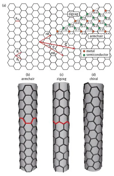
The structure of SWCNTs is characterized by the concept of chirality, which essentially describes the way the graphene layer is wrapped and is represented by a pair of indices (n,m). The integers n and m denote the number of unit vectors (a1, a2) along the two directions in the hexagonal crystal lattice of graphene that result in the chiral vector Cn (Fig. 1.1):
If m = 0, the nanotubes are called “zigzag” nanotubes, if n = m, the nanotubes are defined as “armchair” nanotubes, and all other orientations are called “chiral”. The deviation of Cn from a1 is expressed by the inclination angle θ and ranges from 0° (“armchair”) to 3° (“zigzag”) [17].
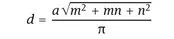
The lattice vector and thus (n, m) can be also used to calculate the tube diameter following
where a = 1.42 × √3 Å = 0.246 nm corresponds to the lattice constant in the graphite sheet (C- C distance for sp2 hybridized carbon: 1.42 Å).
Fig. 1.1: (a) Schematic of unrolled SWCNT showing chiral vector Cn and the effect of m and n on the electronic properties of SWCNTs. (b, c, d) The direction of the chiral vector affects the appearance of the nanotube showing (b) (4,4) armchair, (c) (6,0) zigzag and (d) (5,3) exemplary chiral shape. With kind permission from [18].
1.2.2 Defects
Depending on the synthesis procedure (see Section 1.4) and purification methods (Section 1.6.1), the structure of synthesized carbon nanotubes may include a range of defects (see Chapter 4).
“Topological defects” describe the presence of rings other than hexagons, i.e. pentagons (n5) and heptagons (n7), which result in “kinks” and “elbows” in the usually planar hexagonal carbon layer. Strictly speaking, the fullerene caps are also topological defects as pentagons are essential for a spherical carbon structure. Pentagons and heptagons further accumulate near other defect sites in CNTs [19]. However, no ring sizes other than pentagons and heptagons have yet been observed [20]. Common occurrences of topological defects are pentagon-heptagon pairs directly connected to each other, which are also called Stone–Wales defects. This particular defect structure is more energetically favorable than other combinations [21]. n5 − n7 pairs can also be the center for intramolecular and intermolecular junctions, connecting two parts of one CNT with different helicity or two different CNTs [22]. The density of Stone–Wales defects is typically small due to the high activation barrier for the bond rotation (i.e. few eV). Stone–Wales defects further affect the absorption and charge transfer characteristics and increase strain energy, which leads to enhanced reactivity (i.e. for nucleophilic attack). A related group of defects are dislocations and vacancies. Vacancies can be induced by electron irradiation (e.g. by electron microscopy) and are also centers of enhanced chemical reactivity. On the other hand, vacancies can be annihilated in the presence of neighboring pentagon-heptagon pairs via an atomic exchange mechanism [23].
Although a honeycomb lattice theoretically consists of sp
2 atoms, the carbon’s ability to represent intermediate states of hybridization leads to another kind of defect to counterbalance the strain energy induced by high curvature. This so-called
rehybridization results in a higher
-character of the C-C bonds [24]. Furthermore, local sp
3 hybridization can be induced though chemical treatment, such as after thermal elimination of functional groups.
In general, most of these defects considerably affect the electronic, mechanical and chemical properties of CNTs [25]. For instance, the presence of just one carbon vacancy in the outer (i.e. load-bearing) carbon layer reduces the CNT’s tensile strength by 30% [26]. Defects are also scattering centers that limit the ballistic transport of electrons. However, structural defects on the outer surface of CNTs can also be beneficial when it comes to hybridizing them with metal oxides or other materials. Defects can serve as reaction centers for functionalization and as nucleation sites for crystal growth, influencing both crystallization (i.e. crystal structure, crystal defects) and growth (i.e. size, morphology) of the coating material [27–29].
1.2.3 Doping
Another set of defects is created though the introduction of heteroatoms into CNTs, providing an attractive tool for adjusting their electronic characteristics. Heteroatoms can be incorporated in different ways. An early approach [30] was intercalation between the walls of MWCNTs. This can be achieved ex situ [31–33], i.e. processing ready-made MWCNTs (e.g. annealing in ammonia), or in situ, i.e. during CNT synthesis [30]. In the latter case the experimental procedure depends on the synthesis method employed (see Section 1.5).
Alternatively, carbon atoms in the CNT lattice can be substituted for light elements such as nitrogen or boron (“on-wall doping”) [34], which again can be achieved ex situ or in situ (i.e. using nitrogen-containing carbon precursors in a CVD process). Ex situ substitutional doping requires the removal of a carbon atom and is thus energetically challenging.
The idea of nitrogen doping of carbon materials has been investigated since the 1960s [35]. In graphitic materials like CNTs, nitrogen can be bonded in two ways [36] : In the graphite- like bonding, only one carbon atom is replaced by a nitrogen atom, being covalently bonded to t...