1Pulse width modulation techniques
In power electronic converters, the electrical energy from one level of voltage/ current/ frequency is converted into another using semiconductor-based electronic switch. The essential characteristic of these types of circuits is that the switches are operated only in one of two states – either fully ON or fully OFF – unlike other types of electrical circuits where the control elements are operated in a linear active region.
As the power electronics industry developed, various families of power electronic converters have evolved, often linked by power level, switching devices, and topological origins [3]. Application areas of power converters improved vastly in semiconductor technology, which offer higher voltage and current ratings as well as better switching characteristics. Meanwhile, the main advantages of modern power electronic converters are high efficiency, low weight, small dimensions, fast operation, and high-power densities.
The process of switching the electronic devices in a power electronic converter from one state to another is called ‘modulation’. Each family of power converters has preferred modulation strategies associated with it that aim to optimize the circuit operation for the target criteria most appropriate for that family. Parameters such as switching frequency, distortion, losses, harmonic generation, and speed of response are typical of the issues that must be considered when developing modulation strategies for a particular family of converters. The output voltage of power inverter should be a pure sinusoidal waveform with minimum distortion. However, for practical inverters, the output voltage is a series of rectangular waveforms. The major issues for the control of the power inverters are to get suitable modulation methods to control the output rectangular waveforms to synthesize the desired waveforms. Therefore, a modulation control method is required to get a desired fundamental frequency voltage and to eliminate higher-order harmonics as much as possible.
In modern converters, pulse width modulation (PWM) is a high-speed process ranging depending on the rated power from a few kilohertz (motor control) up to several megahertz (resonant converters for power supply). Therefore, first, we discuss about the principle and different topologies regarding PWM.
1.1Pulse width modulation
The PWM technique is one of the most widely used strategies for controlling the ac output of power electronic converter. In this technique, the duty cycle of converter switches can be varied at a high frequency to achieve a target average low frequency output voltage or current. Modulation theory has been a major research area in power electronics for over three decades and continues to attract considerable attention and interest.
In principle, all modulation schemes aim to create trains of switching pulses that have the same fundamental volt-second average as a target reference waveform at any instant. The major difficulty with these trains of switched pulses is that they also contain unwanted harmonic components that should be minimized. Hence, for any PWM scheme, the primary objective can be identified, which is to calculate the converter switching ON times, which creates the desired (low-frequency) target output voltage or current. Having satisfied this primary objective, the secondary objective for a PWM strategy is to determine the most effective way of arranging the switching process to minimize unwanted harmonic distortion, switching losses, or any other specific performance criterion [7].
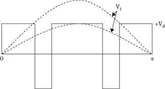
The dc input to the inverter is chopped by switching devices in the inverter. The amplitude and harmonic content of the ac waveform is controlled by varying the duty cycle of the switches. The fundamental voltage V1 has a maximum amplitude of 4 Vd/π for a square wave output, but by creating notches, the amplitude of V1 is reduced.
Usually, the power switches in one inverter leg are always either in ON or OFF state. Therefore, the inverter circuit can be simplified into 3 two-position switches. Either the positive or the negative dc bus voltage is applied to one of the motor phases for a short time. PWM is a method whereby the switched voltage pulses are produced for different output frequencies and voltages. A typical modulator produces an average voltage value, equal to the reference voltage within each PWM period. Considering a very short PWM period, the reference voltage is reflected by the fundamental of the switched pulse pattern. The concept of pulse width modulation is shown in Fig. 1.1.
Fig. 1.1: Principle of pulse width modulation.
There are several different PWM techniques, differing in their methods of implementation. However, in all these techniques, the aim is to generate an output voltage, which after some filtering, would result in a good-quality sinusoidal output voltage waveform of desired fundamental frequency and magnitude. However, in the case of inverters, it may not be possible to reduce the overall voltage distortion due to harmonics, but by proper switching control, the magnitudes of lower-order harmonic voltages can be reduced, often at the cost of increasing the magnitudes of higher order harmonic voltages. Such a situation is acceptable in most cases, as the harmonic voltages of higher frequencies can be satisfactorily filtered using lower sizes of filters and capacitors. Many of the loads, like motor loads, have an inherent quality to suppress high-frequency harmonic currents, and hence, an external filter may not be necessary. To judge the quality of voltage produced by a PWM inverter, a detailed harmonic analysis of the voltage waveform needs to be done.
In fact, after removing a third and multiples of third harmonics from the pole voltage waveform one obtains the corresponding load phase voltage waveform. The pole voltage waveforms of three-phase inverter are simpler to visualize and analyze, and hence, the harmonic analysis of load phase and line voltage waveforms is done via the harmonic analysis of the pole voltages. It is implicit that the load phase and line voltages will not be affected by the third and multiples of third-harmonic components that may be present in the pole voltage waveforms.
1.2Basic pulse width modulation techniques
1.2.1Single pulse width modulation
In single PWM control, the width of the pulse is varied to control the inverter output voltage, and there is only one pulse half per cycle. By comparing the rectangular reference signal with the triangular carrier wave the gating signals are generated, as shown in Fig. 1.2. The frequency of reference signal determines fundamental frequency of the output voltage.
The advantages of this technique are that the even harmonics are absent due to the symmetry of the output voltage along the x-axis and that the Nth harmonics can be eliminated from inverter outp...