Single vehicle "run-of-road" crashes are a significant problem on CAREC roads. They are particularly severe and can occur anywhere and at any time. Identifying, investigating, and treating roadside hazards are significant road safety challenges along CAREC highways. This third manual in the series provides practical information about roadside hazard management for CAREC countries. It uses a roadside hazard management strategy and the clear zone concept to explain how CAREC road authorities can: (i) identify roadside hazards, (ii) investigate how best to treat those roadside hazards, and (iii) implement effective safety improvements. The manual explains the three groups of safety barriers and offers options for safer roadside furniture.
- 74 pages
- English
- ePUB (mobile friendly)
- Available on iOS & Android
eBook - ePub
About this book
Trusted by 375,005 students
Access to over 1.5 million titles for a fair monthly price.
Study more efficiently using our study tools.
Information
V. Using Safety Barriers Correctly
163. In the designs for some new roads, and when improving some existing roads, fixed hazards (such as bridge parapets, supporting piers, or trees with environmental significance) cannot always be avoided within the clear zone. In these situations, after working through the roadside hazard management strategy (delineate, remove, relocate, and modify), the last option is to shield the hazard.
164. Safety barriers improve roadside safety when hazards in the clear zone cannot be removed, relocated, or modified. Safety barriers are designed to safely redirect errant vehicles with reduced injury to vehicle occupants. When compared with impacting a hazardous fixed object, properly designed safety barriers are proven to greatly reduce trauma in a crash.
165. However, when considering whether to install a safety barrier, it is important to understand that the barrier itself will present a hazard to occupants of errant vehicles, and especially to unprotected road users such as motorcyclists. A safety barrier should only be installed if a crash into the barrier will present less of an injury risk to vehicles’ occupants than would result from a crash involving the hazard that is to be shielded. Therefore, the installation of a safety barrier should be the last option in roadside hazard management, not your first.
166. Investment in safety barriers is unusual compared with most other road infrastructure. The life expectancy of a safety barrier can be up to 50 years, and yet it may be in use for only a few seconds during that time. Be sure it works correctly and safely then. And, after that, it needs to be repaired, so a good maintenance regime should be an important concern of the highway agency.
A. Three groups of safety barriers
167. The three main groups of roadside safety barriers are:
• flexible barriers (commonly these are WRSBs);
• semirigid barriers (common semirigid barrier systems include W beam guardrail, box beam, and thrie beam);
• rigid barriers (made of reinforced concrete; there are several profiles).
1. Flexible barriers
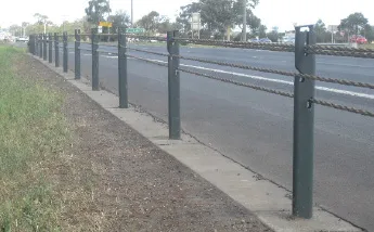
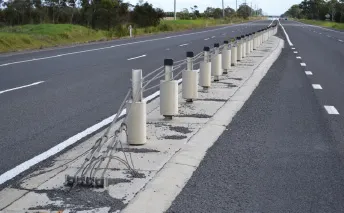
168. The best-known type of flexible barrier, WRSBs are (usually) made of four tensioned wire ropes supported by steel posts (see Figure 5). They are described as flexible because they stretch and absorb the force of the impacting vehicle. The barriers use a dual mechanism to slow down and divert excessive force away from the people inside the vehicle. The ropes deflect and absorb the energy, while the posts collapse, slowing down and redirecting the vehicle away from the hazard with little rebound. Flexible barriers are the most forgiving barrier type, usually allowing the occupants to simply walk away from their crash. Current experience is showing flexible barriers are safer than other available safety barriers.
Figure 5: Two Typical Forms of Wire Rope Safety Barrier
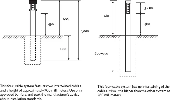
Source: VicRoads. 2016. Road Safety Engineering Workshop handouts.
169. Research conducted by the Monash University Accident Research Centre in Melbourne, Australia shows that flexible barriers are superior to rigid (concrete) barriers and semirigid (steel W beam) barriers because of the way they dissipate the energy of the crash away from the occupants of the vehicle, their deflection levels, and the way they contain the vehicle.
170. WRSB is now considered so successful in reducing the consequences of single vehicle runoff-road crashes in several countries (Australia, New Zealand, Sweden, and the United States) that center line WRSBs are now being introduced. These center line WRSBs are specifically used for, and are proven effective, at preventing head-on crashes.
171. Flexible barrier systems are characterized by relatively high deflections upon impact, which dissipates the energy of a crash. This behavior results in lower injury risk to vehicles’ occupants in comparison with rigid and semirigid barrier systems. Flexible barriers display good control of vehicle trajectories after impact, which assists in redirecting an errant vehicle to a path along the line of the barrier. This minimizes the likelihood of secondary impacts with other vehicles.
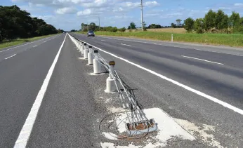
The use of flexible safety barrier along the centerline is becoming a proven method of reducing head-on collisions along two-lane, twoway rural highways, or on wide four-lane highways such as this.
There are several flexible barrier types available. Whichever one chosen, make sure it is an approved type tested by a major standards agency.
Centerline barrier is designed to prevent head-on collisions. It is proving to be beneficial in reducing the risk of these crashes.
Flexible barriers deflect by a great deal when struck. Locating the barrier off the road, but also offset from the hazard by an approved distance, is an essential design consideration to avoid “pocketing.”
172. The offset from the nearest traffic lane should be as generous as can be realistically provided. The ability of a vehicle to stop clear of the traffic lane (for a breakdown, to repair a tire, or for other reasons) is an important factor in the provision of a wide clearance from traffic lane to barrier. It is desirable for the WRSB to be offset from the edge of the nearest traffic lane as follows:
• Desirable minimum offset is 4 m to provide a comfortable width for a vehicle to stop clear of the traffic lane and barrier. This offset also provides a recovery area between the traffic lane and barrier for errant vehicles.
• Minimum offset is 3 m to provide an adequate width for a vehicle to stop clear of the traffic lane and barrier.
• Absolute minimum offset is any offset between 1 m and 3 m. Offsets in this range should be only for short lengths and will usually require highway authority approval.
173. It is desirable to locate flexible safety barriers as far from the edge of the traffic lane as site conditions permit. This will maximize the chance of the driver being able to regain control of the vehicle before impacting the barrier. Nuisance impacts on WRSB systems can be costly for the road authority as their flexible nature allows for greater damage during minor impacts. This can require frequent repair. Remember there is no restriction on the maximum offset of a WRSB from the edge of pavement.
174. The WRSB is to be an approved type, and correctly designed and installed. Due to the higher deflection of the WRSBs relative to other barrier systems, it is important to consider the offset to the hazards to be shielded behind a WRSB (see Table 1).
• WRSBs may be installed on flat ground or on side slopes up to 1V:10H. The maximum lateral slope also applies to the area immediately behind the barrier over which the barrier will deflect, if impacted by a vehicle.
• Generally, a WRSB is not suitable for installation on curves that have a horizontal radius of less than 200 m, as the required rope tension and height may not be maintained during or after an impact. Radii smaller than 200 m have problems with posts being pulled over when the wire rope is tensioned; 200 m is the minimum radius that has been crash-tested.
• WRSBs should generally not be installed on sag vertical curves where the K value is less than 30. With a vertical curve of this size, the wire rope tension may cause the posts at the bottom of the vertical curve to lift out of their sockets. Other concerns are that the errant vehicle may pass beneath the cables, rather than being captured, or that the errant vehicle may become suspended by the tensioned cables at the bottom of dip.
• WRSBs should not be connected directly to semirigid or rigid barriers, including bridge parapets. This is due to a possible vehicle impact with the more rigid barrier (“pocketing”) as an impacting vehicle runs along the deflecting barrier. However, when transitioning to another barrier type, WRSBs may be installed near other barriers with overlapping of barriers to ensure continuity to the next barrier system.
• The minimum length of a WRSB should generally not be less than 24 m at full height or as specified by the manufacturer. The transition length to the end terminal anchors is additional to this minimum length.
Table 1: Approximate Deflection of Wire Rope Safety Barrier
| Post Spacing (m) | Approximate Deflection (m) |
| 1.0 | 1.5 |
| 2.0 | 2.0 |
| 2.5 | 2.5 |
| 3.0 | 2.7 |
| 5.0 | 3.4 |
m = meter.
Source: Federal Highway Administration. 1993. National Cooperative Highway Research Program. Washington, DC.
2. Semirigid barriers
175. Semirigid safety barriers are (mainly) systems that have a steel beam attached to either wooden or steel posts. Semirigid barriers deform or deflect upon impact but to a lesser extent than flexible systems. When stuck by an errant vehicle, the support posts bend and the barrier rail deforms to absorb the force of the impact. The tensile forces developed in the barrier rail assist in redirecting the impacting vehicle.
176. The term “semirigid” was coined because these barriers absorb energy by deflecting during an impact. The maximum amount of de...
Table of contents
- Front Cover
- Title Page
- Copyright Page
- Contents
- Tables and Figures
- Abbreviations
- Purpose of this Manual
- I. An Introduction to Roadside Hazard Management
- II. Identifying Roadside Hazards
- III. Investigating Roadside Hazards: A Roadside Safety Management Strategy
- IV. Treating (Eliminating or Reducing) Roadside Hazards
- V. Using Safety Barriers Correctly
- VI. Other Roadside Safety Furniture
- Glossary of Terms
- Reading List
- Back Cover
Frequently asked questions
Yes, you can cancel anytime from the Subscription tab in your account settings on the Perlego website. Your subscription will stay active until the end of your current billing period. Learn how to cancel your subscription
No, books cannot be downloaded as external files, such as PDFs, for use outside of Perlego. However, you can download books within the Perlego app for offline reading on mobile or tablet. Learn how to download books offline
Perlego offers two plans: Essential and Complete
- Essential is ideal for learners and professionals who enjoy exploring a wide range of subjects. Access the Essential Library with 800,000+ trusted titles and best-sellers across business, personal growth, and the humanities. Includes unlimited reading time and Standard Read Aloud voice.
- Complete: Perfect for advanced learners and researchers needing full, unrestricted access. Unlock 1.5M+ books across hundreds of subjects, including academic and specialized titles. The Complete Plan also includes advanced features like Premium Read Aloud and Research Assistant.
We are an online textbook subscription service, where you can get access to an entire online library for less than the price of a single book per month. With over 1.5 million books across 990+ topics, we’ve got you covered! Learn about our mission
Look out for the read-aloud symbol on your next book to see if you can listen to it. The read-aloud tool reads text aloud for you, highlighting the text as it is being read. You can pause it, speed it up and slow it down. Learn more about Read Aloud
Yes! You can use the Perlego app on both iOS and Android devices to read anytime, anywhere — even offline. Perfect for commutes or when you’re on the go.
Please note we cannot support devices running on iOS 13 and Android 7 or earlier. Learn more about using the app
Please note we cannot support devices running on iOS 13 and Android 7 or earlier. Learn more about using the app
Yes, you can access CAREC Road Safety Engineering Manual 3 by in PDF and/or ePUB format, as well as other popular books in Technology & Engineering & Civil Law. We have over 1.5 million books available in our catalogue for you to explore.