![]()
PART I
Review of Electric and Magnetic Circuit Theory
![]()
Chapter 1
Basic Electric Circuit Theory
1.1Review of Basic Equations of Electric Circuit Theory
In circuit theory, there are two distinct types of basic mathematical relations. In the first type, these relations depend on the physical nature of circuit elements and they are called terminal relations. The second type of relations reflects the connectivity of the electric circuit, namely, how the circuit elements are interconnected. For this reason, they are sometimes called topological relations. These relations are based on the Kirchhoff Current Law (KCL) and Kirchhoff Voltage Law (KVL).
We start with terminal relations and consider five basic two-terminal elements: resistor, inductor, capacitor and ideal (independent) voltage and current sources. These circuit elements are ubiquitous in power engineering applications. However, in power electronics, multi-terminal circuit elements are used as well. These multi-terminal circuit elements are models of power semiconductor devices and they will be discussed in Chapter 1 of Part III.
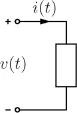
A two-terminal element is schematically represented in Figure 1.1. Each two-terminal element is characterized by the voltage v(t) across the terminals and by the current i(t) through the element. In order to write the meaningful equations relating the voltages and currents in electric circuits, it is necessary to assign a polarity to the voltage and a direction to the current. These assigned (not actual) directions and polarities are called reference directions and reference polarities. These reference directions and polarities are assigned arbitrarily. The actual current directions and voltage polarities are not known beforehand and they may change with time. The reference direction for a current is indicated by an arrow, while the reference polarity is specified by placing plus and minus signs next to element terminals (see Figure 1.1). The reference directions and polarities are usually coordinated by choosing the reference direction of the current from the positive reference terminal to the negative reference terminal.
Fig. 1.1
As discussed below, the reference directions and polarities are used in writing KCL and KVL equations. These equations are then solved and the signs of currents and voltages are found at any instant of time. If at time t a current is positive,
then the actual direction of this current coincides with its reference direction. If, on the other hand, the found current is negative at time t,
then the actual direction of this current at time t is opposite to its reference direction.
Similarly, if a voltage is found to be positive,
then the actual polarity coincides with its reference polarity. On the other hand, if the voltage is found to be negative,
then the actual voltage polarity is opposite to its reference polarity. It is clear from the above discussion that the reference directions and polarities allow one to write KCL and KVL equations, then solve them and eventually find actual directions and polarities of circuit variables.
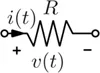
Now, we consider a resistor. Its circuit notation is shown in Figure 1.2. The terminal relation for the resistor is given by Ohm’s law,
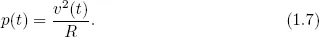
where R is the resistance of the resistor. By using the terminal relation (1.5), we find the expression for instantaneous power p(t) for the resistor,
Fig. 1.2
Fig. 1.3
or
It is clear from the last two equations that in the case of the resistor the instantaneous power is always positive, which means that the re...