- 148 pages
- English
- ePUB (mobile friendly)
- Available on iOS & Android
Clinical Electrocardiography
About this book
Since the publication of the 3rd Edition 17 years ago, progress has been truly remarkable in all areas of electrocardiography. Five of the seven chapters in this 4th Edition have been extensively revised. Out of the total of 125 ECGs, 65 are new. Each ECG is crisp and clear and all the abnormalities are highlighted by arrows for easy recognition and understanding. This book is the culmination of the author's 45 years of experience in the teaching of electrocardiography to coronary care unit nurses, medical undergraduates, postgraduates, interns, residents, senior residents and above. As the title of the book implies, the approach to the subject has been entirely from the viewpoint of a clinician. Hence, clinical-electrocardiographic correlations have been emphasized simply and succinctly throughout the text.
Request Inspection Copy
Readership: Medical undergraduates, doctors, nurses and cardiology registrars.
Tools to learn more effectively

Saving Books

Keyword Search

Annotating Text

Listen to it instead
Information
CHAPTER 1
THE NORMAL ELECTROCARDIOGRAM
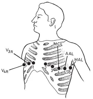
1 to 6 = leads V1 to V6.
MCL = mid-clavicular line,
AAL = anterior axillary line,
MAL = mid-axillary line,
V3R and V4R = right-sided chest leads. See text.
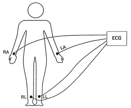
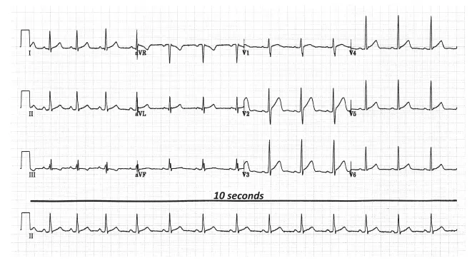
The 12-LEAD ELECTROCARDIOGRAM
CALCULATION OF HEART RATE
Box Counting Method
| Heart Rate | Number of Large Boxes between 2 Consecutive Beats |
| 300 | 1 (300/1) |
| 150 | 2 (300/2) |
| 100 | 3 (300/3) |
| 75 | 4 (300/4) |
| 60 | 5 (300/5) |
| 50 | 6 (300/6) |
| 43 | 7 (300/7) |
| 38 | 8 (300/8) |
QRS Counting Method
Calculating QRS Axis
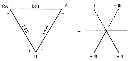
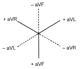
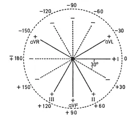
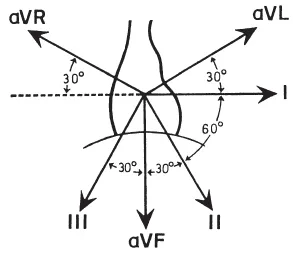
Table of contents
- Cover page
- Title page
- Copyright page
- Dedication
- Foreword
- Preface
- Acknowledgements
- CONTENTS
- 1. The Normal Electrocardiogram
- 2. Ischaemic Heart Disease
- 3. Miscellaneous Conditions
- 4. Cardiac Arrhythmias
- 5. Supraventricular Arrhythmias
- 6. Ventricular Arrhythmias
- 7. Bundle Branch Block, Hemiblock and Atrioventricular (AV) Block
- Index
Frequently asked questions
- Essential is ideal for learners and professionals who enjoy exploring a wide range of subjects. Access the Essential Library with 800,000+ trusted titles and best-sellers across business, personal growth, and the humanities. Includes unlimited reading time and Standard Read Aloud voice.
- Complete: Perfect for advanced learners and researchers needing full, unrestricted access. Unlock 1.4M+ books across hundreds of subjects, including academic and specialized titles. The Complete Plan also includes advanced features like Premium Read Aloud and Research Assistant.
Please note we cannot support devices running on iOS 13 and Android 7 or earlier. Learn more about using the app