- 132 pages
- English
- ePUB (mobile friendly)
- Available on iOS & Android
Energy Methods in Stress Analysis
About this book
This book builds the subject from a foundation that static equilibrium occurs when the rate of change of work done by the load is equal to the rate of change of strain energy in the structure,
Energy methods are a powerful tool for the stress analysis of loaded structures. This book builds the subject from a foundation that static equilibrium occurs when the rate of change of work done by the load is equal to the rate of change of strain energy in the structure. Advanced applications of the method are easily developed from this fundamental principle by partial differentiation of the appropriate terms.
The methods solve linear problems, statically indeterminate structures, non-linear problems, frames and the derivation of stiffness matrices used in finite element analysis. Critical buckling loads for struts, plates and panels are modelled by comparison of the strain energy stored in the unbuckled and buckled shapes. This method develops an interesting discussion on the theory of buckling of a long slender strut which is additional to those in traditional texts. Post buckling stiffness of plates and panels are modelled using assumed shapes for strain energy calculation. The presentation offers a clear reasoning leading to analysis possibilities not seen in traditional texts which espouse concepts of virtual work, minimum potential energy, complementary energy, and the unit load method.
Tools to learn more effectively

Saving Books

Keyword Search

Annotating Text

Listen to it instead
Information


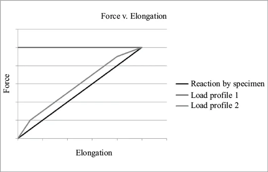
- The reaction exerted by the rod through its elongation range.
- The curve “Load profile 1” is the applied load slowly increasing. The load increases such that it always slightly greater than the reaction up to the final point of static equilibrium where they are equal.
- The curve “Load profile 2” is an applied load being equal to the final value of “Load profile 1” and constant through the elongation of the specimen.
Table of contents
- Cover
- halftile
- Title
- copyright
- Abstract
- Contents
- List of Figures
- 01_Chapter 1
- 02_Chapter 2
- 03_Chapter 3
- 04_Chapter 4
- 05_Chapter 5
- 06_Chapter 6
- 07_Chapter 7
- 08_Chapter 8
- 09_Chapter 9
- 10_Chapter 10
- 11_Chapter 11
- 12_Chapter 12
- 13_Chapter 13
- 14_Chapter 14
- 15_Chapter 15
- 16_Chapter 16
- 17_Chapter 17
- 18_Chapter 18
- 19_Chapter 19
- 20_Chapter 20
- 21_Chapter 21
- 22_Chapter 22
- 23_Index
- 24_Adpage
Frequently asked questions
- Essential is ideal for learners and professionals who enjoy exploring a wide range of subjects. Access the Essential Library with 800,000+ trusted titles and best-sellers across business, personal growth, and the humanities. Includes unlimited reading time and Standard Read Aloud voice.
- Complete: Perfect for advanced learners and researchers needing full, unrestricted access. Unlock 1.4M+ books across hundreds of subjects, including academic and specialized titles. The Complete Plan also includes advanced features like Premium Read Aloud and Research Assistant.
Please note we cannot support devices running on iOS 13 and Android 7 or earlier. Learn more about using the app