![]()
Chapter 1
Introduction
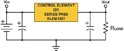
Increased awareness of global warming has accelerated research into harnessing renewable energy and the development of energy-efficient power conversion systems. The proliferation of renewable energy-based systems and hybrid electric and all-electric vehicles has increased the magnitude of energy processed by power electronics. The heart of any power electronic circuit is the power semiconductor device. Using the semiconductor device as a switch in a power electronic circuit allows components to operate at higher efficiency and power rating. Before power electronic circuits were developed, DC voltage was regulated by using a linear regulator. Figure 1 shows the basic schematic of a linear regulator circuit.
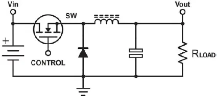
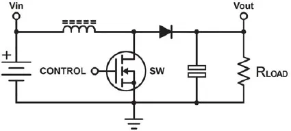
The output voltage is regulated by adjusting the voltage drop across the control element which is usually a semiconductor transistor. A linear regulator has two major drawbacks: the first limitation of a linear regulator is that the voltage drop across the series pass element caused significant losses in the circuit. The second limitation of a linear regulator is that the circuit could only step down the DC voltage. Switching regulators are well known for their high efficiency (typically >90%) and compact form factor. Depending on the topology, switching regulators can be used to either step down the DC voltage using a Buck converter (Fig. 2) or step up the DC voltage using a Boost converter (Fig. 3). The selection of optimum switching frequency for the power semiconductor device (SW) is based on the application and type of semiconductor device.1,2
The following is a list of applications, with primary focus on renewable energy, which are heavily dependent on modern-day power semiconductor devices to ensure efficient and optimum performance.
Fig. 1.Simplified schematic of linear regulator.
Fig. 2.Simplified schematic of Buck converter.
Fig. 3.Simplified schematic of Boost converter.
•Wind Energy System
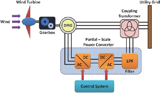
Wind energy systems consist of rectifier and inverter circuits which operate in unison to regulate the power flow. Commercial grid-connected wind turbines are implemented based on the two most commonly used topologies, namely Doubly Fed Induction Generator (DFIG)-based design and Direct-Drive design. Figure 4 shows the schematic block diagram of a DFIG-based wind turbine configuration. The DFIG-based wind turbine is a popular system in which the power electronic interface controls the rotor current to achieve the variable speed necessary for maximum energy generation at variable wind speed. Since the power electronics only has to process the rotor power, typically less than 30% of the overall output power, DFIG offers the advantages of speed control with reduced cost and power losses.3–5
Fig. 4.Simplified schematic of DFIG-based wind turbine.
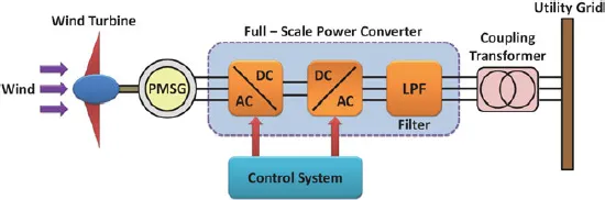
Figure 5 shows the schematic block diagram of a Direct-Drive wind turbine system. The AC voltage output from the wind turbine is converted to DC by a rectifier circuit. The DC voltage is then converted back to AC voltage by an inverter circuit. The output voltage from the inverter is stepped up to the grid-compatible voltage by a transformer and fed to the utility grid. One of the major differences between a DFIG-based and Direct-Drive wind turbine is the absence of a gearbox in the Direct-Drive system. In this configuration, power electronics must be capable of handling the total power output of the wind turbine, which can be of the order of several megawatts (MW). This could introduce severe electrothermal stress on the power semiconductor devices used in the system. Hence, power semiconductors devices utilized in wind energy systems must be capable of handling high voltage and high current.6–8
Fig. 5.Simplified schematic of Direct-Drive wind turbine.
•Photovoltaic Energy System
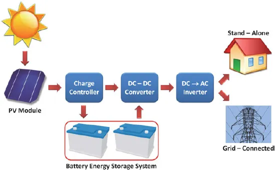
Power electronic circuits are also used extensively in Photovoltaic (PV) energy harvesting systems. PV energy systems can be classified into types based on their configuration: stand-alone or off-grid systems and grid-connected or utility-interactive systems. Stand-alone systems are designed and configured to operate independent of the electric grid and are usually installed to meet the power demands of a small residential community or individual home. Grid-connected PV systems are configured to operate in unison with the electric grid and can be designed for power rating up to several MW. The general block diagram of a PV energy system is shown in Fig. 6. The output from a solar panel is a DC voltage and current. The charge controller incorporates Maximum Power Point Tracking (MPPT) algorithm to extract maximum power from the PV modules. The DC voltage from the charge controller is conditioned using a DC–DC converter to the appropriate voltage level and is converted to AC by a power electronic inverter circuit.9 The power semiconductors in the circuit must be capable of handling the peak output power from the PV system. Due to the intermittent nature of solar energy, it is imperative to have a Battery Energy Storage System (BESS) to provide power backup.10
Figure 6 shows a typical battery system when connected to the grid as a part of the PV energy system. A similar BESS can also be implemented in a wind energy system due to the intermittent nature of the energy source. The power electronics in a battery system must be bidirectional. When the battery is discharging, an inverter circuit is used to convert the DC power from the battery to AC for connection to the grid. When the battery is being charged from the grid, the AC power is converted to DC by a rectifier circuit. In the PV energy system shown in Fig. 6, the battery charging is handled by the charge controller unit. Again, power semiconductor devices are used to manage the flow of energy.9
Fig. 6.Simplified block diagram of PV energy system.
•Hybrid Electric Vehicle
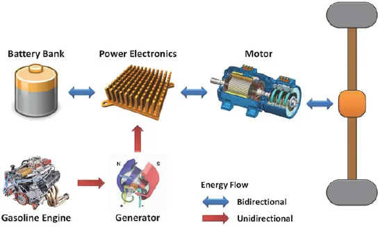
Hybrid Electric Vehicles (HEV) can be classified based on their drive train architecture: Series, Parallel, and Series–Parallel. Detailed discussion of HEV architectures are beyond the scope of this textbook. The block diagram of series hybrid electric drive train is shown in Fig. 7. The power electronics system work the same way as the grid-connected battery system. During vehicle operation, the power electronics circuitry converts DC power from the battery to AC power for the traction motors. The battery bank gets charged either through a generator driven by a small gasoline engine or by an external charging system. HEVs are also designed to charge the battery bank using energy captured from the motor during regenerative braking of the vehicle. Bidirectional energy transfer and management of the battery system are done by the power semiconductor devices.11,12
In an all-electric vehicle, the role of power electronics is even more important since the absence of an internal combustion engine is compensated by a high-energy density BESS. The power electronic circuit must be able to operate under the high-temperature condition encountered in an automobile while processing the full rated power of the vehicle. The power semiconductor devices utilized in automotive applications must have high performance and reliability throughout the lifespan of the vehicle.13
Fig. 7.Simplified block diagram of series hybrid electric drive train.
•Other Applications
Another fast emerging area for the high-current power device is data centers. Data centers require reliable energy systems to maintain the availability of the data. Data centers are currently powered by low-voltage and high-current systems. Power electronics are used to process the high-current power to the load. Data centers also require battery backup for high-reliability operation.14,15 Another application is in the area of pulsed power system. Unlike continuous power systems, pulsed power systems charge up over a long period of time and discharge the energy over a short period of time. Power semiconductor switches are used in the following two areas of pulsed power systems: out...