This book is a profound compendium on strain gages and their application in materials science and all fields of engineering. It covers both the theoretical and practical aspects of strength and stress analysis using the technique of strain gages. A brief historical review about strain gage inventions is looking at the "who, when and how". The comprehensive bibliography leads to additional background information.
Particular consideration is given to the stress analysis in order to verify the mechanical properties and capacity of components with focus on stability and serviceability, optimization, and safety checks, as well as in order to foresee inspection and monitoring. The practice-oriented descriptions of the principles of the measurement, installation and experimental set-ups derives from the author`s own experiences in the field. Particular emphasis is laid on the correct planning and assessment of measurements, and on the interpretation of the results. Step-by-step guidance is given for many application examples, and comments help to avoid typical mistakes.
The book is an indispensable reference work for experts who need to analyze structures and have to plan measurements which lead to reliable results. The book is instructive for practitioners who must install reliable measurement circuits and judge the results. The book is also recommended for beginners to get familiar with the problems and to learn about the possibilities and the limits of the strain gage technique.

eBook - ePub
Technology and Practical Use of Strain Gages
With Particular Consideration of Stress Analysis Using Strain Gages
- English
- ePUB (mobile friendly)
- Available on iOS & Android
eBook - ePub
Technology and Practical Use of Strain Gages
With Particular Consideration of Stress Analysis Using Strain Gages
About this book
Trusted by 375,005 students
Access to over 1.5 million titles for a fair monthly price.
Study more efficiently using our study tools.
Information
1
Historical Review
It is an irrefutable fact that the strain gage was invented by two different people at almost the same time. They were situated at widely separated places in the USA and they did not, at that time, have any contact with each another [1.1]. Professor Arthur C. Ruge of the Massachusetts Institute of Technology (MIT) was one of these inventors; the other was Edward E. Simmons. At the California Institute of Technology (Caltech) in 1936, Simmons was investigating the stress–strain behaviour of metals under shock loads. He was at the time a student and worked as a research assistant at the Institute.
To measure the force introduced in the specimens by impact, he used a dynamometer equipped with fine resistance wires made from constantan. The tests carried out by Simmons were part of a research project of Dätwyler and Clark that started in 1936 [1.2]. Although details of the tests and the measurement method used were not published until 1938 [1.3], the start date of the project (1936) shows that it was Simmons who invented the strain gage principle. Publication about the tests and the used measurement method was divulged not before 1938 [1.3]. In 1940, Simmons's invention was patented at the United States Patent Office. Figure 1.1 shows the test equipment that Simmons used for the measurement of shock loads on metal specimens. The dynamometer is equipped with measuring wires made from constantan. The drawing is taken from the Patent [1.4]. This shows that a strain gage based transducer was patented before the strain gage itself.
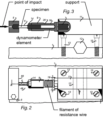
Fig. 1.1 E.E. Simmons's dynamometer equipped with measuring wires for the measuring of shock loads on metal specimens [1.4]
In 1938 the other inventor, Professor Arthur C. Ruge, with the support of his assistant J. Hanns Maier investigated in the field of engineering seismology the influence of earthquakes on mechanical structures. His test object was a small scale model of an elevated water tank, mounted on a vibration table. However, because the stress was low and the model's skin extremely thin they failed to measure the strain in the tank wall using normal mechanical or optical strain instrumentation available at that time. One day the saving idea came to him, and he attached the thin wire from a potentiometer with Duo household cement to the water tank and was immediately rewarded with excellent and reproducible measurement values.
The resistance change in metallic wires caused by strain due to tensile loading changed the voltage drop in the wire and could be measured with a simple bridge circuit [1.5, 1.6]. The strain gage was now born also on the east coast of the USA.
Figure 1.2 shows a photograph taken by J. Hanns Maier of Professor Ruge carrying out experiments on the model of a water tank using the first strain gages invented by him and his assistant Maier. Strain gage rosettes are cemented to the model's base. Also visible in the photograph is an acceleration transducer made by Ruge using resistance wires.
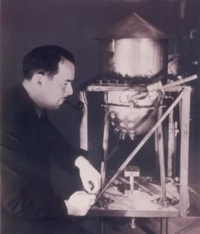
Fig. 1.2 A.C. Ruge carrying out experiments on a small scale model of a water tank fitted with the first strain gages mounted on a vibration table in 1938
For easier handling Ruge cemented the measuring wire to a carrier paper that had been stiffened by cementing the paper to two Plexiglas end pieces with a brass spacer bar serving as a handling frame and lead wire holder. The brass spacer bar was removed after cementing. Figure 1.3 shows one of the first strain gages made by Ruge with and without brass bar and with the felt protection layer removed. The strain gage seen in Figure 1.3 was patented in 1944 [1.7].
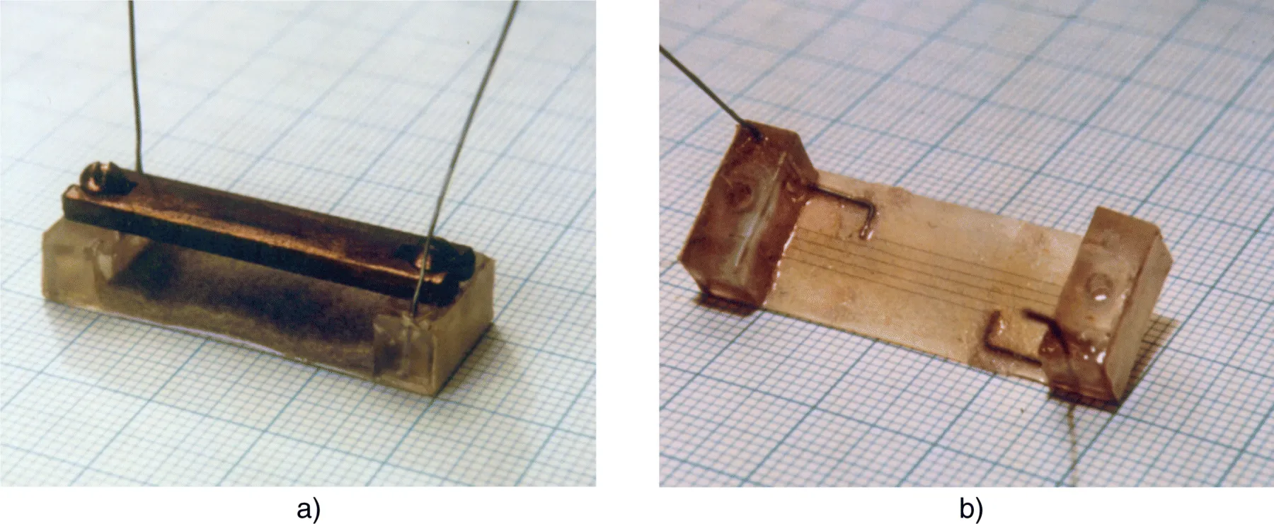
Fig. 1.3 Ruge's strain gage from 1938 a) with brass bar as an installation aid b) without brass bar and without grid protection layer
In 1938 in accordance with custom, Ruge duly submitted the bonded wire ‘resistant strain gage’ idea to the MIT patent committee. The committee's answer deserves quoting. The reply of the MIT reads: ‘…this development is interesting; the Committee does not feel that the commercial use is likely to be of major importance...any rights which the Institute may have in this invention should be waived in your favour…’ [1.8]. This meant that Ruge was free to exploit the invention as his own.
In 1939, Ruge and his colleague Professor Alfred V. deForest, with support of the heavy machine construction firm Baldwin-Southwark Corp. started the manufacture and sale of strain gages. The first answer by Baldwin-Southwark to Ruge's licence offer is also worthy of note: ‘We are in the locomotive business and not going to make postage stamps’ [1.6]. But after a convincing demonstration of strain gage performance in 1939, a profitable cooperation started between Ruge-deForest and Baldwin-Southwark. The beginning was marked by the registration of the strain gage. The invention was patented by the United States Patent Office on June 6 in 1944. When, in 1955, Ruge-deForest sold out to Baldwin-Lima-Hamilton, at that stage they employed more than 200 people.
Before the patent registration of Ruge's invention, Baldwin-Southwark arranged an agreement between Simmons and Ruge-deForest that recognized Simmons as well as Ruge as inventor of the strain gage [1.6]. At the end of the discussion which led to the agreement, Tatnall suggested in a spirit of fun that the new product be named SR-4; S and R for Simmons and Ruge, and the numeral 4 representing the four people who took part in the final discussion (Tatnall as instigator of the discussion, Clark as colleague of Simmons from Caltech, deForest as Ruge's colleague from MIT and Hathaway as patent attorney from Baldwin). This designation was registered as a trademark.
Figure 1.4 shows an SR-4 strain gage with paper carrier as it was when it became world-famous. It can be seen from Figure 1.4 that the SR-4 strain gage bears the number 2 292 549 of Simmon's patent. After the SR-4 agreement a legal battle ensued between Simmons and Caltech for whom Simmons was working when he made the invention. Caltech claimed they sponsored the development and asked a 60/40 split on royalties. Caltech lost the case, because, at the time the invention was made, Simmons was a student and not on the Caltech payroll.
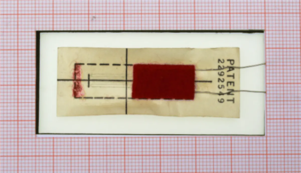
Fig. 1.4 SR-4 strain gage with paper carrier from 1941 the protective felt layer is half removed
In 1939, Ruge and deForest started their partnership with Baldwin-Southwark for development engineering and manufacture of strain gages and strain gage devices for sale. In 1941, they got the first solid sizeable order from Baldwin for stock gages – 50 000 in one order for all types. These were intended to last a year, but actually lasted two month. Figure 1.5 shows one of the first strain gage packages as sold in that time.
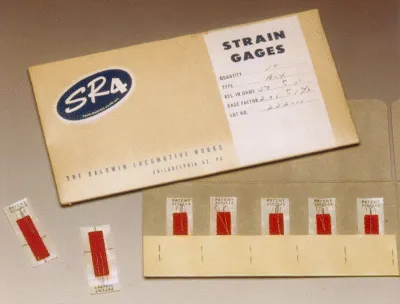
Fig. 1.5 One of the first strain gage packages as sold by Baldwin in 1941
Simmons and Ruge were not the first scientists to recognize the resistance change in metallic wires caused by tensile loading and the possibility of using this phenomenon to measure mechanical quantities...
Table of contents
- Cover
- Title Page
- Copyright
- Preface
- Chapter 1: Historical Review
- Chapter 2: Fundamentals of Strain Gage Technology
- Chapter 3: Installation of Strain Gages
- Chapter 4: The Wheatstone Bridge Circuit
- Chapter 5: Adjustment and Compensation Circuits
- Chapter 6: Cable Between the Strain Gage Bridge Circuit and Measuring Instrument
- Chapter 7: Signal Processing
- Chapter 8: Calibration of Devices for Measuring with Strain Gages
- Chapter 9: Determination of mechanical stresses from strains measured with strain gages
- Chapter 10: Application examples of elastic deformation
- Chapter 11: Determination of Thermal Stresses
- Chapter 12: Strain Gages as a Means for Experimental Determination of Residual Stresses
- Chapter 13: Stress Analysis Using Strain Gages in the Elastoplastic Deformation Range
- Chapter 14: Strength Theories
- Index
- End User License Agreement
Frequently asked questions
Yes, you can cancel anytime from the Subscription tab in your account settings on the Perlego website. Your subscription will stay active until the end of your current billing period. Learn how to cancel your subscription
No, books cannot be downloaded as external files, such as PDFs, for use outside of Perlego. However, you can download books within the Perlego app for offline reading on mobile or tablet. Learn how to download books offline
Perlego offers two plans: Essential and Complete
- Essential is ideal for learners and professionals who enjoy exploring a wide range of subjects. Access the Essential Library with 800,000+ trusted titles and best-sellers across business, personal growth, and the humanities. Includes unlimited reading time and Standard Read Aloud voice.
- Complete: Perfect for advanced learners and researchers needing full, unrestricted access. Unlock 1.5M+ books across hundreds of subjects, including academic and specialized titles. The Complete Plan also includes advanced features like Premium Read Aloud and Research Assistant.
We are an online textbook subscription service, where you can get access to an entire online library for less than the price of a single book per month. With over 1.5 million books across 990+ topics, we’ve got you covered! Learn about our mission
Look out for the read-aloud symbol on your next book to see if you can listen to it. The read-aloud tool reads text aloud for you, highlighting the text as it is being read. You can pause it, speed it up and slow it down. Learn more about Read Aloud
Yes! You can use the Perlego app on both iOS and Android devices to read anytime, anywhere — even offline. Perfect for commutes or when you’re on the go.
Please note we cannot support devices running on iOS 13 and Android 7 or earlier. Learn more about using the app
Please note we cannot support devices running on iOS 13 and Android 7 or earlier. Learn more about using the app
Yes, you can access Technology and Practical Use of Strain Gages by Stefan Keil in PDF and/or ePUB format, as well as other popular books in Technology & Engineering & Civil Engineering. We have over 1.5 million books available in our catalogue for you to explore.