Design of Steel Structures for Buildings in Seismic Areas
Eurocode 8: Design of Structures for Earthquake Resistance. Part 1: General Rules, Seismic Action and Rules for Buildings
,
English
ePUB (mobile friendly)
Available on iOS & Android
eBook - ePub
Design of Steel Structures for Buildings in Seismic Areas
Eurocode 8: Design of Structures for Earthquake Resistance. Part 1: General Rules, Seismic Action and Rules for Buildings
,
About this book
This volume elucidates the design criteria and principles for steel structures under seismic loads according to Eurocode 8-1. Worked Examples illustrate the application of the design rules. Two case studies serve as best-practice samples.
Trusted by 375,005 students
Access to over 1.5 million titles for a fair monthly price.
Chapter 1 Seismic Design Principles in Structural Codes
1.1 INTRODUCTION
Earthquake Engineering is the branch of engineering aiming at mitigating risks induced by earthquakes with two objectives: i) to predict the consequences of strong earthquakes on urban areas and civil infrastructures; ii) to design, build and maintain structures that are able to withstand earthquakes in compliance with building codes.
Researchers and experts working within emergency management organizations (e.g. the civil protection) actively work on the first issue. On the contrary, structural designers focus their attention and efforts on the second objective. With this regard, it should be noted that the seismic design philosophy substantially differs from the design approaches conventionally adopted for other types of actions, raising difficulties to structural engineers less confident with seismic engineering. Indeed, broadly speaking, for quasi-static loads (e.g. dead and live loads, wind, snow, etc.) the structure should behave mostly elastically without any damage until the maximum loads are reached, while in case of seismic design it is generally accepted that structures can experience damage because they should perform in the plastic range for seismic events. The philosophy of structural seismic design establishes the performance levels that properly engineered structures should satisfy for different seismic intensities, which can be summarized as follows:
– prevent near collapse or serious damage in rare major ground shaking events, which are called in the following Ultimate Limit State seismic action or ULS seismic action;
– prevent structural damage and minimize non-structural damage in occasional moderate ground shaking events;
– prevent damage of non-structural components (such as building partitions, envelopes, facilities) in frequent minor ground shaking events.
Hence, the most meaningful performance indexes for seismic resistant structures are the amount of acceptable damage and the repair costs. Owing to the unforeseeable nature of seismic actions, it is clear that damage control is very difficult to be quantified by code provisions, especially because it is related to acceptable levels of risk. The challenge for efficient design of seismic resistant structures is to achieve a good balance between the seismic demand (namely the effect that earthquakes impose on structures) and the structural capacity (namely the ability to resist seismic induced effects without failure). However, the quantification of different types of damage (structural and non-structural) associated to the reference earthquake intensity (e.g. frequent/minor, occasional/moderate, and rare/major) and the definition of relevant operational design criteria are still open issues that need clarification and further studies.
This chapter describes and discusses the concept of capacity design in the light of existing seismic codes, illustrating the evolution of seismic design principles throughout time, and explains the criteria that form the basis of EN 1998-1:2004 (CEN, 2004a), henceforth denoted as EC8-1.
1.2 FUNDAMENTALS OF SEISMIC DESIGN
1.2.1 Capacity design
It is generally acknowledged that structural safety depends on the ductility that the structural system can provide against the design loads. Indeed, ductility represents the capacity of a mechanical system (e.g. a beam, a structure, etc.) to deform in the plastic domain without substantially reducing its bearing capacity.
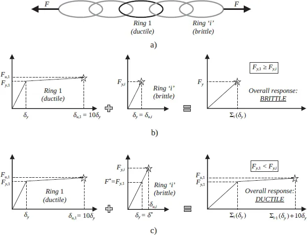
In seismic design of structures it is generally not economical or possible to ensure that all the elements of the structure behave in a ductile manner. Inevitably, a dissipative (ductile) structure comprises both dissipative (ductile) elements and non-dissipative (brittle) ones. In order to achieve a dissipative (ductile) design for the whole structure, the failure of the brittle elements must be prevented. This may be done by prioritizing structural elements strength, which will lead to the prior yielding of ductile structural elements, preventing the failure of brittle structural elements. This principle is known as ”capacity design”. Capacity design may be explained by considering the chain model, introduced by Paulay and Priestley (1992) and depicted in Figure 1.1a, whereby the chain represents a structural system made of both ductile elements (e.g. the ring “1”) and brittle zones (e.g. the ring “i”).
According to non-seismic design procedures for quasi-static loads (hereinafter referred to as “direct design”), the design force is the same for all elements belonging to the chain, because the applied force is equal for all rings, being a system in series. Hence, the design resistance Fy,i is the same for all elements. Under this assumption, the yield resistance of the ductile chain Fy,1 is equal or even slightly larger than Fy,i.
Figure 1.1 – Ductility of a chain with brittle and ductile rings
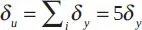
As shown in Figure 1.1b, with the direct design approach the system cannot develop strength larger than Fy and the ultimate elongation of the chain is given as
(1.1)
According to capacity design principles, in order to improve the ductility of the chain, some rings should be designed with ductile behaviour and lower strength, as is the case of ring “1” in Figure 1.1c. The remaining rings “i” that are brittle should be designed to provide a resistance Fy,i larger than the maximum resistance Fu,1 exhibited by the ring “1” beyond yielding. The ductile ring “1” behaves as a sacrificial element, i.e. a ductile fuse, which filters the external actions and limits the transfer of forces into the brittle elements. Hence, the maximum force that the chain can sustain is equal to the maximum resistance Fu,1 of the ductile ring “1”. It is interesting to observe that the beneficial improvement of the capacity design methodology is the increase of displacement capacity, given as follows:
(1.2)
Comparing equations (1.1) and (1.2), it can be easily recognized that the collapse displacement of the chain is significantly larger than that obtained by adopting the direct design approach.
This trivial example allows to understand that the brittle elements represent protected zones that must be designed to resist larger forces than those supported by the ductile elements. Those larger forces do not directly depend on the external applied loads but they are obtained from the maximum capacity of the connected ductile elements. However, it should be emphasized that the external forces are used to design the dissipative elements, which establish the threshold of structural strength.
Concerning the practical application to building structures, this methodology leads the structural designers to work on two different schemes for the same structure, as follows:
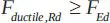
1) elastic behaviour with the calculation of the relevant internal forces FEd to design the dissipative elements. Hence, following an elastic analysis, the ductile structural elements should satisfy the following check:
(1.3)
In addition to strength, the ductile elements must possess a ductility corresponding to the chosen ductility class. The ductility is provided by using appropriate structural details and different materials and specific design principles for specific types of structures;
2) inelastic response with design of non-dissipative (i.e. brittle) elements on the basis of the plastic strength of the connected dissipative parts. Hence, in order to prevent their failure, brittle elements must be sized so that they present an over strength with respect to the capacity of the ductile elements, as follows:
(1.4)
where Ω is a coefficient (> 1.0) that takes into account different aspects that may lead to ductile elements strengths larger than the design ones (strain hardening phenomena, material strength larger than the nominal values, etc.).
This twofold approach is the basic characteristic of capacity design and represents the main distinctive difference with respect to direct design for quasistatic actions. The example shown in Figure 1.1 also allows understanding that the common belief of non-seismic designers, which consider that the excess of strength is always beneficial and safe, may dramatically impair the non-linear response of a structure either by overdesigning the fuse elements or, with more serious consequences, by inaccurate quality control of the material properties that results in larger strength for the dissipative elements (e.g. a steel element conceived as fuse with grade S355 is supplied with higher grade as S460). The consequence of such events is clear, namely the failure of the system because the hierarchy of resistance is not complied with.
In case of steel structures the best way to dissipate energy is to exploit the tensile capacity of the material, which can be obtained by enforcing plasticity into specific zones called plastic hinges that can involve either flexural, tensile or shear mechanisms depending on the type of adopted structural scheme (e.g. moment resisting frame, concentrically or eccentrically braced frame), while preserving the rest of the structure from damage.
1.2.2 Seismic design concepts
Two substantially different concepts can be used to design structures located in seismic areas, which correspond to two different structural behaviours:
The difference between dissipative and non-dissipative behaviours is dictated by bo...
Table of contents
Cover
Table of Contents
Foreword
Preface
Chapter 1: Seismic Design Principles in Structural Codes
Chapter 2: EN 1998-1: General and Material Independent Parts
Chapter 3: EN 1998-1: Design Provisions for Steel Structures
Chapter 4: Design Recommendations for Ductile Details
Chapter 5: Design Assisted by Testing
Chapter 6: Multi-storey Building with Moment Resisting Frames
Chapter 7: Multi-storey Building with Concentrically Braced Frames
Chapter 8: Multi-storey Building with Eccentrically Braced Frames
Chapter 9: Case Studies
References
End User License Agreement
Frequently asked questions
Yes, you can cancel anytime from the Subscription tab in your account settings on the Perlego website. Your subscription will stay active until the end of your current billing period. Learn how to cancel your subscription
No, books cannot be downloaded as external files, such as PDFs, for use outside of Perlego. However, you can download books within the Perlego app for offline reading on mobile or tablet. Learn how to download books offline
Perlego offers two plans: Essential and Complete
Essential is ideal for learners and professionals who enjoy exploring a wide range of subjects. Access the Essential Library with 800,000+ trusted titles and best-sellers across business, personal growth, and the humanities. Includes unlimited reading time and Standard Read Aloud voice.
Complete: Perfect for advanced learners and researchers needing full, unrestricted access. Unlock 1.5M+ books across hundreds of subjects, including academic and specialized titles. The Complete Plan also includes advanced features like Premium Read Aloud and Research Assistant.
Both plans are available with monthly, semester, or annual billing cycles.
We are an online textbook subscription service, where you can get access to an entire online library for less than the price of a single book per month. With over 1.5 million books across 990+ topics, we’ve got you covered! Learn about our mission
Look out for the read-aloud symbol on your next book to see if you can listen to it. The read-aloud tool reads text aloud for you, highlighting the text as it is being read. You can pause it, speed it up and slow it down. Learn more about Read Aloud
Yes! You can use the Perlego app on both iOS and Android devices to read anytime, anywhere — even offline. Perfect for commutes or when you’re on the go. Please note we cannot support devices running on iOS 13 and Android 7 or earlier. Learn more about using the app
Yes, you can access Design of Steel Structures for Buildings in Seismic Areas by in PDF and/or ePUB format, as well as other popular books in Tecnologia e ingegneria & Ingegneria civile. We have over 1.5 million books available in our catalogue for you to explore.

 In addition to strength, the ductile elements must possess a ductility corresponding to the chosen ductility class. The ductility is provided by using appropriate structural details and different materials and specific design principles for specific types of structures;
 where Ω is a coefficient (> 1.0) that takes into account different aspects that may lead to ductile elements strengths larger than the design ones (strain hardening phenomena, material strength larger than the nominal values, etc.).