Design of Joints in Steel and Composite Structures
eBook - ePub

Design of Joints in Steel and Composite Structures

Eurocode 3: Design of Steel Structures. Part 1-8 Design of Joints. Eurocode 4: Design of Composite Steel and Concrete Structures. Part 1-8 Design of Joints

,
  1. English
  2. ePUB (mobile friendly)
  3. Available on iOS & Android
eBook - ePub

Design of Joints in Steel and Composite Structures

Eurocode 3: Design of Steel Structures. Part 1-8 Design of Joints. Eurocode 4: Design of Composite Steel and Concrete Structures. Part 1-8 Design of Joints

,
Book details
Book preview
Table of contents
Citations

About This Book

This book details the basic concepts and the design rules included in Eurocode 3

  • Design of steel structures: Part 1-8
  • Design of joints
  • Joints in composite construction are also addressed through references to Eurocode 4
  • Design of composite steel and concrete structures
  • Part 1-1: General rules and rules for buildings.

Attention has to be duly paid to the joints when designing a steel or composite structure, in terms of the global safety of the construction, and also in terms of the overall cost, including fabrication, transportation and erection. Therefore, in this book, the design of the joints themselves is widely detailed, and aspects of selection of joint configuration and integration of the joints into the analysis and the design process of the whole construction are also fully covered.

Connections using mechanical fasteners, welded connections, simple joints, moment-resisting joints and lattice girder joints are considered. Various joint configurations are treated, including beam-to-column, beam-to-beam, column bases, and beam and column splice configurations, under different loading situations (axial forces, shear forces, bending moments and their combinations).

The book also briefly summarises the available knowledge relating to the application of the Eurocode rules to joints under fire, fatigue, earthquake, etc., and also to joints in a structure subjected to exceptional loadings, where the risk of progressive collapse has to be mitigated.

Finally, there are some worked examples, plus references to already published examples and to design tools, which will provide practical help to practitioners.

Frequently asked questions

Simply head over to the account section in settings and click on “Cancel Subscription” - it’s as simple as that. After you cancel, your membership will stay active for the remainder of the time you’ve paid for. Learn more here.
At the moment all of our mobile-responsive ePub books are available to download via the app. Most of our PDFs are also available to download and we're working on making the final remaining ones downloadable now. Learn more here.
Both plans give you full access to the library and all of Perlego’s features. The only differences are the price and subscription period: With the annual plan you’ll save around 30% compared to 12 months on the monthly plan.
We are an online textbook subscription service, where you can get access to an entire online library for less than the price of a single book per month. With over 1 million books across 1000+ topics, we’ve got you covered! Learn more here.
Look out for the read-aloud symbol on your next book to see if you can listen to it. The read-aloud tool reads text aloud for you, highlighting the text as it is being read. You can pause it, speed it up and slow it down. Learn more here.
Yes, you can access Design of Joints in Steel and Composite Structures by in PDF and/or ePUB format, as well as other popular books in Technology & Engineering & Civil Engineering. We have over one million books available in our catalogue for you to explore.

Information

Publisher
Ernst & Sohn
Year
2016
ISBN
9783433604786
Edition
1

Chapter 1
INTRODUCTION

1.1 GENERAL

1.1.1 Aims of the book

The aim of the present book is threefold:
  1. – To provide designers with practical guidance and tools for the design of steel and composite joints;
  2. – To point out the importance of structural joints on the response of steel and composite structures and to show how the actual behaviour of joints may be incorporated into the structural design and analysis process;
  3. – To illustrate the possibilities of producing more economical structures using the new approaches offered in Eurocode 3 and Eurocode 4 as far as structural joints are concerned.
The organisation of the book reflects the belief that, in addition to the sizing of the members (beams and columns), consideration should also be given to the joint characteristics throughout the design process. This approach, despite the novelty it may present to many designers, is shown to be relatively easy to integrate into everyday practice using present day design tools.
Hence the present book addresses design methodology, structural analysis, joint behaviour and design checks, at different levels:
  1. – Presentation and discussion of concepts;
  2. – Practical guidance and design tools.

1.1.1.1 The traditional common way in which joints are modelled for the design of a frame

Generally speaking, the process of designing building structures has been up to now made up of the following successive steps:
  1. – Frame modelling including the choice of rigid or pinned joints;
  2. – Initial sizing of beams and columns;
  3. – Evaluation of internal forces and moments (load effects) for each ultimate limit state (ULS) and serviceability limit state (SLS) load combination;
  4. – Design checks of ULS and SLS criteria for the structure and the constitutive beams and columns;
  5. – Iteration on member sizes until all design checks are satisfactory;
  6. – Design of joints to resist the relevant members end forces and moments (either those calculated or the maximum ones able to be transmitted by the actual members); the design is carried out in accordance with the prior assumptions (frame modelling) on joint stiffness.
This approach was possible since designers were accustomed to considering the joints to be either pinned or rigid only. In this way, the design of the joints became a separate task from the design of the members. Indeed, joint design was often performed at a later stage, either by other personnel or by another company.
Recognising that most joints have an actual behaviour which is intermediate between that of pinned and rigid joints, Eurocode 3 and Eurocode 4 offer the possibility to account for this behaviour by opening up the way to what is presently known as the semi-continuous approach. This approach offers the potential for achieving better and more economical structures.

1.1.1.2 The semi-continuous approach
The rotational behaviour of actual joints is well recognised as being often intermediate between the two extreme situations, i.e. rigid or pinned.
In sub-chapter 1.2, the difference between joints and connections will be introduced. For the time being, examples of joints between one beam and one column only will be used.
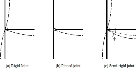
Let us now consider the bending moments and the related rotations at a joint (Fig. 1.1):
images
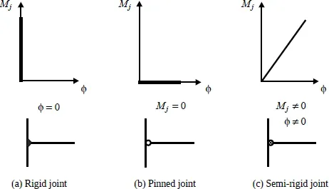
Figure 1.1 – Classification of joints according to stiffness
When all the different parts in the joint are sufficiently stiff (i.e. ideally infinitely stiff), the joint is rigid, and there is no difference between the respective rotations at the ends of the members connected at this joint (Fig. 1.1a). The joint experiences a single global rigid-body rotation which is the nodal rotation in the commonly used analysis methods for framed structures.
Should the joint be without any stiffness, then the beam will behave just as a simply supported beam, whatever the behaviour of the other connected member(s) (Fig. 1.1b). This is a pinned joint.
For intermediate cases (non-zero and non-infinite stiffness), the transmitted moment will result in a difference ϕ between the absolute rotations of the two connected members (Fig. 1.1c). The joint is semi-rigid in these cases.
The simplest way for representing this concept is a rotational (spiral) spring between the ends of the two connected members. The rotational stiffness Sj of this spring is the parameter that links the transmitted moment Mj to the relative rotation ϕ, which is the difference between the absolute rotations of the two connected members.
When this rotational stiffness Sj is zero, or when it is relatively small, the joint falls back into the pinned joint class. In contrast, when the rotational stiffness Sj is infinite, or when it is relatively high, the joint falls into the rigid joint class. In all the intermediate cases, the joint belongs to the semi-rigid joint class.
images
Figure 1.2 – Modelling of joints (case of elastic global analysis)
For semi-rigid joints the loads will result in both a bending moment Mj and a relative rotation ϕ between the connected members. The moment and the relative rotation are related through a constitutive law depending on the joint properties. This is illustrated in Figure 1.2 where, for the sake of simplicity, an elastic response of the joint is assumed in view of the structural analysis to be performed (how to deal with non-linear behaviour situations will be addressed later on, especially in chapter 2).
It shall be understood that the effect, at the global analysis stage, of having semi-rigid joints instead of rigid or pinned joints is to modify not o...

Table of contents

  1. Cover
  2. Table of Contents
  3. Series
  4. Title
  5. Copyright
  6. FOREWORD
  7. PREFACE
  8. LIST OF SYMBOLS AND ABBREVIATIONS
  9. Chapter 1: INTRODUCTION
  10. Chapter 2: STRUCTURAL ANALYSIS AND DESIGN
  11. Chapter 3: CONNECTIONS WITH MECHANICAL FASTENERS
  12. Chapter 4: WELDED CONNECTIONS
  13. Chapter 5: SIMPLE JOINTS
  14. Chapter 6: MOMENT RESISTANT JOINTS
  15. Chapter 7: LATTICE GIRDER JOINTS
  16. Chapter 8: JOINTS UNDER VARIOUS LOADING SITUATIONS
  17. Chapter 9: DESIGN STRATEGIES
  18. BIBLIOGRAPHIC REFERENCES
  19. Annex A: Practical values for required rotation capacity
  20. Annex B: Values for lateral torsional buckling strength of a fin plate
  21. End User License Agreement