eBook - ePub
Handbook of Tunnel Engineering II
Basics and Additional Services for Design and Construction
- English
- ePUB (mobile friendly)
- Available on iOS & Android
eBook - ePub
Handbook of Tunnel Engineering II
Basics and Additional Services for Design and Construction
About this book
Tunnel engineering is one of the oldest, most interesting but also challenging engineering disciplines and demands not only theoretical knowledge but also practical experience in geology, geomechanics, structural design, concrete construction, machine technology, construction process technology and construction management. The two-volume "Handbuch des Tunnel- und Stollenbaus" has been the standard reference work for German-speaking tunnellers in theory and practice for 30 years. The new English edition is based on a revised and adapted version of the third German edition and reflects the latest state of knowledge. The book is published in two volumes, with the second volume covering both theoretical themes like design basics, geological engineering, structural design of tunnels and monitoring instrumentation, and also the practical side of work on the construction site such as dewatering, waterproofing and scheduling as well as questions of tendering, award and contracts, data management and process controlling. As with volume I, all chapters include practical examples.
Trusted by 375,005 students
Access to over 1.5 million titles for a fair monthly price.
Study more efficiently using our study tools.
Information
1
General Principles for the Design of the Cross-section
1.1 General
The shape and size of the design cross-section derive firstly from the purpose of the tunnel (rail tunnel, road tunnel, sewer, water tunnel or pressure tunnel for a hydropower station) and thus the required clearance gauge. Secondly, the dimensions will also be influenced, as is the alignment, by the geotechnical or structural conditions in the ground to be passed through; whether earth or water pressure could occur or whether no external loading is to be expected. Thirdly, the construction process also has an effect on the design of the cross-section; for a given clearance gauge, the most economic cross-section is that which can be constructed with the least excavation and support technology and with the optimal machinery, taking into account the given basic shape.
1.2 Dependence on intended use
1.2.1 Road tunnels
General. The traffic conditions in a road tunnel should in principle correspond to those in the open air. Road tunnels are, however, special sections of a road and demand stringent requirements for their construction, maintenance and operation. Road tunnels have to meet particular requirements regarding road safety and operational safety. When the needs of traffic management are balanced against economy, it is therefore necessary and justifiable in many cases to limit the speed compared to parts of the road in the open air. The permitted maximum speed is thus normally limited to 80 km/h in road tunnels, which inevitably differentiates the traffic flow in tunnels from roads in the open air.
Tunnel cross-section. Road tunnels with two-way traffic and those with one-way traffic are fundamentally different. Two-way tunnels normally consist of a single tube with one lane in each direction. In one-way tunnels, the traffic in each direction is constructionally separated, for example through the provision of two bores. While in the past each bore was often laid out with two lanes without a hard shoulder, the changing composition of the traffic and ever increasing traffic loading will also demand three lanes without hard shoulder, and in exceptional cases even three lanes with a hard shoulder.
The design of the cross-section of road tunnels has to consider road traffic aspects, operational equipment and the tunnel structure. The design of the cross-section of a cut-and-cover road tunnel is often subject to different constraints from a mined underground tunnel. Some examples of cross-sections of mined road tunnels are shown in Fig. 1-1.
Figure 1-1 Cross-sections of some mined road tunnels.
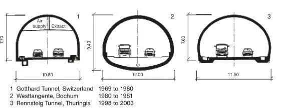
The starting point of all considerations does, of course, remain the space required for the road intended to run through the tunnel. The required total cross-section can often be twice that of the actual cross-section for traffic, and the cross-sectional area at breakdown bays of autobahn tunnels can be up to 200 m2 and more. The space required is also influenced by the horizontal and vertical alignments selected for the project.
The design of tunnel cross-sections in Germany is based on the guidelines for the equipment and operation of road tunnels (RABT) [77], also taking into account the guidelines for road design; cross-sections (RAS-Q) [76] and alignment (RAS-L) [75]. These guidelines include requirements for the standard cross-section, the structure or vehicle gauge to be maintained, the transverse and longitudinal gradients in tunnels and the provision of breakdown bays and emergency exits.
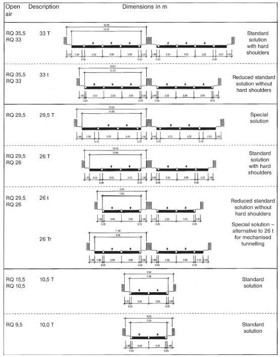
Standard cross-section. The standard cross-section of a road tunnel has to provide dimensions to enable the installation of equipment like lighting, ventilation, traffic management and safety technology, normally outside the clearance gauge. Particularly ventilation and signage equipment may demand an enlargement of the tunnel cross-section. In order to limit the multitude of possible cross-sections – also for economic reasons – the standard cross-sections of roads in the open air are assigned to road cross-section types in tunnels. The selection of road tunnel cross-sections is carried out according to [33] (Fig. 1-2).
In tunnels intended for two-way traffic, the standard cross-section type 10,5 T with 7.50 m paved width between the kerbs is normally provided. This cross-section is also used in open-air sections where wider verges are provided due to high heavy goods traffic volumes. In the course of a road with 2 + 1 RQ 15,5 sections (two lanes with an overtaking lane), sections running through tunnels are also constructed to section 10,5 T. The over-taking lane in this case thus has to be terminated in good time before the tunnel. Special solutions like an additional crawler or climbing lanes in the tunnel are an exception. When in exceptional cases tunnel sections on main roads only provide RQ 9,5 section, crosssection 10,0 T should be used [33].
The normal layout in tunnels with multi-lane carriageways in one direction should be a reduced standard road section without hard shoulders (26 t or 33 t), although it is justifiable under certain economic or traffic conditions to provide hard shoulders. Economic aspects in this case could be the construction and operating costs resulting from the length of the tunnel or the costs resulting from congestion and accidents. The hard shoulders are available for vehicles to swerve to the side or stop in an emergency. They often allow continued multi-lane traffic flow after minor accidents or breakdowns and also simplify maintenance work without serious disruption of traffic flow. The width of hard shoulders varies depending on cross-section type (Fig. 1-2). It is
| – for cross-section type | 29,5 T | 2.50 m. |
| – for cross-section types | 26 T and 33 T | 2.00 m. |
| – for cross-section type | 26 Tr | 1.50 m. |
Figure 1-2 Standard cross-sections for road tunnels [33, 77].
For the layout of hard shoulders in tunnels, reference should be made to [33]. Using this decision-making process, it should be checked whether the additional utility resulting from a hard shoulder exceeds its extra cost. Using the diagrams for use with this process, it can be seen that the decision to provide the cross-sections with hard shoulders (26 T or 33 T) can only be justified under very favourable construction conditions or with a high volume of heavy good vehicle traffic combined with steep gradients. This process applies for multi-lane carriageways in one direction in road tunnel up to 2,000 m long.
The reduced form of special cross-section 26 Tr should only be considered for tunnels to be driven with shield machines. In this case, the reduced hard shoulder replaces the other-wise necessary breakdown bays along the entire length [33].
Cross-section type 29,5 T is only worth considering for very unusual cases and in any case only for very short tunnels with an exceptionally low-cost construction method.
Clearance gauge, traffic gauge. The clearance gauge denotes the space for the road cross-section, which has to be kept clear of obstructions. It consists of the traffic gauge and the safety margins at the top and the sides. The necessary cross-sectional area of the clearance gauge ensues from the traffic purpose of the tunnel. It is derived from the applicable standard cross-section in the open air; the permissible restriction of the cross-section inside structures also has to be considered (RAS-Q [76]).
The total width of the clearance gauge is the sum of the widths of the side safety margins, the carriageway, the verges and any additional lanes (for example hard shoulders) (Fig. 1-3).
Figure 1-3 Outline of the clearance gauge in road tunnels (standard solution) [77].
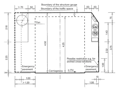
The required headroom for road traffic is 4.50 m. For economic reasons, the sides of the outline are normally vertical, demanding a widening of the safety margin when the cross-slope gradient is steep. For circular cross-sections, on the other hand, it can be economic to tilt the clearance gauge with the carriageway. The outline at the sides can then be assumed to be vertical to the carriageway. It is not necessary in such cases to widen the safety margin.
The outline of the clearance gauge includes areas solely reserved for traffic. Emergency pavements are provided on each side of the carriageway, which are 1.00 m wide and have to have clear headroom of 2.25 m. These are separated from the carriageway with kerbs, normally 7 cm high. Part areas are assigned at a height > 2.25 m above the emergency side pavements, in which easily deformable furniture elements particularly traffic signs and notices can be located although these are only permitted to approach within 50 cm of the traffic gauge; jet fans required for ventilation have to be installed in niches or ceiling coves. Easily deformable light fittings are only permitted to approach within 50 cm of the traffic gauge at a height of > 3.75 m. If jet fans are located inside the normal structural dimensions, this results in widenings of the emergency pavements dependent on the diameter of the fans to be installed [77].
It is often practical to locate traffic signs on the end walls of breakdown bays. In exceptional cases, traffic signs can by located down to a minimum of 30 cm from the traffic gauge at a height > 2.25 m above the emergency pavements; but this does not apply where a widening of the emergency pavement has been provided for fans. If traffic signs have to be made with smaller dimensions than stated in the regulations [32], then this has to be agreed with the authority responsible for traffic management.
Light fittings are permitted to approach within 50 cm of the traffic gauge in exceptional cases when it can be ensured that a clear headroom of 4.10 m from the top of the emergency pavement to the underside of the light fitting is maintained at all points. Jet fans with external diameters ≤ 70 cm are permitted in exceptional cases to be located in the safety margin with a minimum distance at the side of ≥ 30 cm to the traffic gauge in the upper corners.
Gradient and cross-slope. According to the RAS-L [75], the gradient in uninhabited areas running through tunnels should be limited to 4 % if possible and a maximum of 2.5 % should be the intention, particularly for longer distances. The chimney effect, which also increases with increasing gradient, normally leads to higher longitudinal flow, which in case of fire can severely impair the rapid and effective removal of smoke by a ventilation system. In order to ensure road safety and due to the chimney effect, gradients steeper than 5 % should be avoided in road tunnels in uninhabited areas.
A minimum cross-slope of 2.5 % is spe...
Table of contents
- Cover
- Table of Contents
- Title Page
- Author
- Copyright
- Dedication
- The authors
- Foreword to the English edition
- Foreword to the 3rd German edition
- Foreword to the 2nd German edition
- Foreword to the 1st German edition
- 1 General Principles for the Design of the Cross-section
- 2 Engineering geology aspects for design and classification
- 3 Structural design verifications, structural analysis of tunnels
- 4 Measurement for monitoring, probing and recording evidence
- 5 Dewatering, waterproofing and drainage
- 6 New measurement and control technology in tunnelling
- 7 Special features of scheduling tunnel works
- 8 Safety and safety planning
- 9 Special features in tendering, award and contract
- 10 Process controlling and data management
- 11 DAUB recommendations for the selection of tunnelling machines
- Bibliography
- Index
Frequently asked questions
Yes, you can cancel anytime from the Subscription tab in your account settings on the Perlego website. Your subscription will stay active until the end of your current billing period. Learn how to cancel your subscription
No, books cannot be downloaded as external files, such as PDFs, for use outside of Perlego. However, you can download books within the Perlego app for offline reading on mobile or tablet. Learn how to download books offline
Perlego offers two plans: Essential and Complete
- Essential is ideal for learners and professionals who enjoy exploring a wide range of subjects. Access the Essential Library with 800,000+ trusted titles and best-sellers across business, personal growth, and the humanities. Includes unlimited reading time and Standard Read Aloud voice.
- Complete: Perfect for advanced learners and researchers needing full, unrestricted access. Unlock 1.5M+ books across hundreds of subjects, including academic and specialized titles. The Complete Plan also includes advanced features like Premium Read Aloud and Research Assistant.
We are an online textbook subscription service, where you can get access to an entire online library for less than the price of a single book per month. With over 1.5 million books across 990+ topics, we’ve got you covered! Learn about our mission
Look out for the read-aloud symbol on your next book to see if you can listen to it. The read-aloud tool reads text aloud for you, highlighting the text as it is being read. You can pause it, speed it up and slow it down. Learn more about Read Aloud
Yes! You can use the Perlego app on both iOS and Android devices to read anytime, anywhere — even offline. Perfect for commutes or when you’re on the go.
Please note we cannot support devices running on iOS 13 and Android 7 or earlier. Learn more about using the app
Please note we cannot support devices running on iOS 13 and Android 7 or earlier. Learn more about using the app
Yes, you can access Handbook of Tunnel Engineering II by Bernhard Maidl,Markus Thewes,Ulrich Maidl in PDF and/or ePUB format, as well as other popular books in Technology & Engineering & Civil Engineering. We have over 1.5 million books available in our catalogue for you to explore.