- English
- ePUB (mobile friendly)
- Available on iOS & Android
Direct Eigen Control for Induction Machines and Synchronous Motors
About this book
Clear presentation of a new control process applied to induction machine (IM), surface mounted permanent magnet synchronous motor (SMPM-SM) and interior permanent magnet synchronous motor (IPM-SM)
Direct Eigen Control for Induction Machines and Synchronous Motors provides a clear and consise explanation of a new method in alternating current (AC) motor control. Unlike similar books on the market, it does not present various control algorithms for each type of AC motor but explains one method designed to control all AC motor types: Induction Machine (IM), Surface Mounted Permanent Magnet Synchronous Motor (SMPM-SM) (i.e. Brushless) and Interior Permanent Magnet Synchronous Motor (IPM-SM). This totally new control method can be used not only for AC motor control but also to control input filter current and voltage of an inverter feeding an AC motor.
- Accessible and clear, describes a new fast type of motor control applied to induction machine (IM), surface mounted permanent magnet synchronous motor (SM-PMSM) and interior permanent magnet synchronous motor (I-PMSM) with various examples
- Summarizes a method that supersedes the two known direct control solutions – Direct Self Control and Direct Torque Control – to be used for AC motor control and to control input filter current and voltage of an inverter feeding an AC motor
- Presents comprehensive simulations that are easy for the reader to reproduce on a computer. A control program is hosted on a companion website
This book is straight-forward with clear mathematical description. It presents simulations in a way that is easy to understand and to reproduce on a computer, whilst omitting details of practical hardware implementation of control, in order for the main theory to take focus. The book remains concise by leaving out description of sensorless controls for all motor types. The sections on "Control Process", "Real Time Implementation" and "Kalman Filter Observer and Prediction" in the introductory chapters explain how to practically implement, in real time, the discretized control with all three types of AC motors. In order, this book describes induction machine, SMPM-SM, IPM-SM, and, application to LC filter limitations. The appendixes present: PWM vector calculations; transfer matrix calculation; transfer matrix inversion; Eigen state space vector calculation; and, transition and command matrix calculation.
Essential reading for Researchers in the field of drive control; graduate and post-graduate students studying electric machines; electric engineers in the field of railways, electric cars, plane surface control, military applications. The approach is also valuable for Engineers in the field of machine tools, robots and rolling mills.
Tools to learn more effectively

Saving Books

Keyword Search

Annotating Text

Listen to it instead
Information
1
Induction Machine
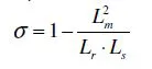
1.1 Electrical Equations and Equivalent Circuits
1.1.1 Definitions and Notation
| Rs |
| Rr |
| ls |
| lr |
| Lm |
| Ls = Lm + ls |
| Lr = Lm + lr |
|  |
|  |
| Np |
|  |
- mechanical angular frequency of the rotor Ω
- polar mechanical angular frequency1 ω = Np ⋅ Ω
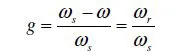
- stator electrical angular frequency ωs
- rotor electrical angular frequency ωr
- relative slip
1.1.2 Equivalent Electrical Circuits
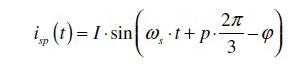
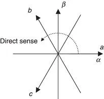
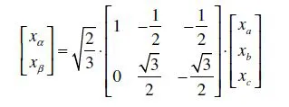
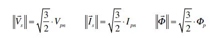
- the phase–neutral instantaneous voltage, per phase:
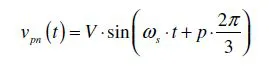
- the instantaneous current in each phase:

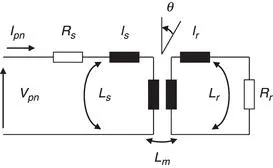
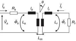
1.1.3 Differential Equation System
Table of contents
- Cover
- Title page
- Copyright page
- Dedication
- Foreword by Prof. Dr Ing. Jean-Luc Thomas
- Foreword by Dr Abdelkrim Benchaïb
- Acknowledgements
- Introduction
- 1 Induction Machine
- 2 Surface-Mounted Permanent-Magnet Synchronous Motor
- 3 Interior Permanent Magnet Synchronous Motor
- 4 Inverter Supply – LC Filter
- 5 Conclusion
- Appendix A: Calculation of Vector PWM
- Appendix B: Transfer Matrix Calculation
- Appendix C: Transfer Matrix Inversion
- Appendix D: State-Space Eigenvector Calculation
- Appendix E: F and G Matrix Calculations
- References
- Index
Frequently asked questions
- Essential is ideal for learners and professionals who enjoy exploring a wide range of subjects. Access the Essential Library with 800,000+ trusted titles and best-sellers across business, personal growth, and the humanities. Includes unlimited reading time and Standard Read Aloud voice.
- Complete: Perfect for advanced learners and researchers needing full, unrestricted access. Unlock 1.4M+ books across hundreds of subjects, including academic and specialized titles. The Complete Plan also includes advanced features like Premium Read Aloud and Research Assistant.
Please note we cannot support devices running on iOS 13 and Android 7 or earlier. Learn more about using the app