eBook - ePub
Classical and Modern Mechanisms for Engineers and Inventors
Preben W. Jensen
This is a test
- 616 Seiten
- English
- ePUB (handyfreundlich)
- Über iOS und Android verfügbar
eBook - ePub
Classical and Modern Mechanisms for Engineers and Inventors
Preben W. Jensen
Angaben zum Buch
Buchvorschau
Inhaltsverzeichnis
Quellenangaben
Über dieses Buch
Jensen (mechanical engineering, Mankato State U., Minn.) is a prolific designer/interpreter/reporter of mechanisms for the user of mechanical movements. This collection offers solutions or inspirations in some 20 areas including the slider crank, cycloid, screw and clamping mechanisms, antibacklash
Häufig gestellte Fragen
Wie kann ich mein Abo kündigen?
Gehe einfach zum Kontobereich in den Einstellungen und klicke auf „Abo kündigen“ – ganz einfach. Nachdem du gekündigt hast, bleibt deine Mitgliedschaft für den verbleibenden Abozeitraum, den du bereits bezahlt hast, aktiv. Mehr Informationen hier.
(Wie) Kann ich Bücher herunterladen?
Derzeit stehen all unsere auf Mobilgeräte reagierenden ePub-Bücher zum Download über die App zur Verfügung. Die meisten unserer PDFs stehen ebenfalls zum Download bereit; wir arbeiten daran, auch die übrigen PDFs zum Download anzubieten, bei denen dies aktuell noch nicht möglich ist. Weitere Informationen hier.
Welcher Unterschied besteht bei den Preisen zwischen den Aboplänen?
Mit beiden Aboplänen erhältst du vollen Zugang zur Bibliothek und allen Funktionen von Perlego. Die einzigen Unterschiede bestehen im Preis und dem Abozeitraum: Mit dem Jahresabo sparst du auf 12 Monate gerechnet im Vergleich zum Monatsabo rund 30 %.
Was ist Perlego?
Wir sind ein Online-Abodienst für Lehrbücher, bei dem du für weniger als den Preis eines einzelnen Buches pro Monat Zugang zu einer ganzen Online-Bibliothek erhältst. Mit über 1 Million Büchern zu über 1.000 verschiedenen Themen haben wir bestimmt alles, was du brauchst! Weitere Informationen hier.
Unterstützt Perlego Text-zu-Sprache?
Achte auf das Symbol zum Vorlesen in deinem nächsten Buch, um zu sehen, ob du es dir auch anhören kannst. Bei diesem Tool wird dir Text laut vorgelesen, wobei der Text beim Vorlesen auch grafisch hervorgehoben wird. Du kannst das Vorlesen jederzeit anhalten, beschleunigen und verlangsamen. Weitere Informationen hier.
Ist Classical and Modern Mechanisms for Engineers and Inventors als Online-PDF/ePub verfügbar?
Ja, du hast Zugang zu Classical and Modern Mechanisms for Engineers and Inventors von Preben W. Jensen im PDF- und/oder ePub-Format sowie zu anderen beliebten Büchern aus Tecnología e ingeniería & Ingeniería industrial. Aus unserem Katalog stehen dir über 1 Million Bücher zur Verfügung.
Information
1
Five Basic Mechanisms
The design engineer is often faced with the problem of finding a mechanism for a given purpose or of changing a mechanism to make it more suitable for the purpose. It is his primary objective to find the simplest possible solutions based on the three criteria: space, speed, and savings.
An introduction to mechanisms begins with a review of the foundation of kinematics, namely, the concept of joints. A joint connects two links. There are five joints with one degree of freedom. One degree of freedom means that one coordinate describes the position of one link relative to the other link. The five basic joints are
Turning joint: The relative motion between the two links is a rotation.
Sliding joint: The relative motion between the two links is a translation. Theoretically the bar and the hole could have constant radius of curvature along the axis, but this kind of sliding joint is rarely used in practice.
Rolling joint: This type of joint permits the two links to roll on each other without sliding. The joint takes on two forms: the gear joint and the band joint, where the connection is maintained by two bands, each band being wrapped around both links. Both gear and band joints include noncircular surfaces. The joints can be interchanged without resulting change in motion.
Table 1.1
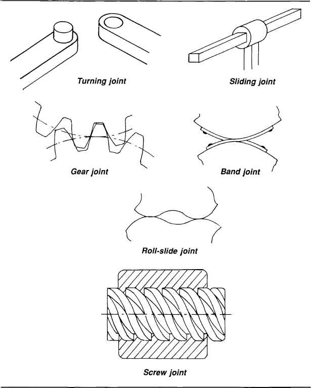
Roll-slide joint: The two links are kept in contact by force closure. The joint has two points of contact. For special proportions form closure can be achieved (see Fig. 1.6).
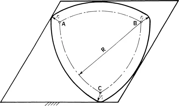
Figure 1.6 A roll-slide mechanism
Screw joint: This is the well-known screw and nut. The relative motion between the links is a combined turning and translating motion.
In general the four-bar linkage and mechanisms that can be derived from the four-bar linkage are considered the simplest mechanisms. This assumption, however, does not always lead to the best mechanism design solution. In the literature joints are defined as connecting links of a mechanism. What is not recognized is that some of them should be considered mechanisms in their own right. Examples will be shown of how joint mechanisms can replace far more complicated mechanisms and result in patentable devices. The turning-joint mechanism, described later is especially impressive because of its simplicity and speed, which could not be achieved with a more complex mechanism having more links.
The Screw Mechanism
Archimedes (287–212 B.C.) had an inclination for practical applications of mathematical principles.* A short time after his arrival in Egypt, Archimedes invented the screw pump. He had been surprised with the amount of work people and animals performed in order to pump water from the Nile onto the fields. He decided to improve the impractical pumps that had been used for thousands of years, and he designed a wooden screw, as shown in Fig. 1.1. When he dipped this device into the Nile and started rotating it, it immediately started pumping. A paddle wheel was used as the driving means, so that the river provided power for the pumping action itself.
The Sliding-Joint Mechanism
A sliding joint is an irregular-shaped shaft sliding in a hole with identical cross section. In the literature this joint is designated a sliding joint and is not considered a mechanism. For practical purposes it can be a piston in a cylinder. An application of this joint is described later in the chapter.
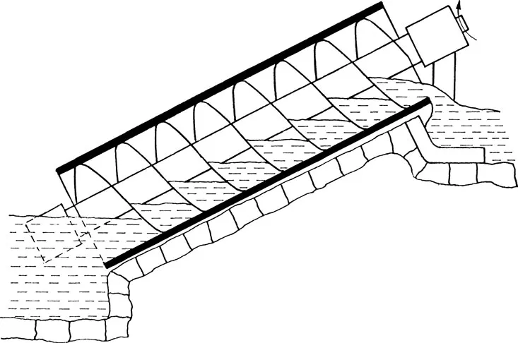
Figure 1.1 Archimedes’ water pump.
The Turning-Joint Mechanism
The turning-joint mechanism is, in principle, just a pin on one link and a corresponding hole in the neighboring link. In the literature it is called a turning joint, or revolute pair, and is not referred to as a mechanism. First, a complex solution to cutting material on-the-fly will be shown. This device was invented many years ago. Then, a device in the form of a turning-joint mechanism will be shown that does the same but is much simpler and much faster.
Cutoff Device for Cigarettes
Continuously moving material can be cut without stopping the material, thus speeding production. Conventionally, this type of cutting is done while moving the tool at the same velocity as the material and then withdrawing the cutter and returning it to the starting position and repeating the operation.
The principle is illustrated by the device in Fig. 1.2. The material to be cut moves at constant velocity. A circular knife on a shaft is supported by a cutter carrier, which swings in a circular path on a pair of equal-length cranks. The cranks are driven at the same angular velocity by one or both of the connected crankshafts. When the right-hand crank is rotated, a bevel gear fixed to the crank drives a second gear fixed to the cutter spindle and revolves the knife. The cutter carrier has a nonrotating shafts, which imparts a reciprocating motion through a sleeve bushing to a slide supporting the material while it is being cut. Since the cutter and work move in the same direction at the same speed, it is not possible to change the length of the cutoff piece without reproportioning of the device. Because of the large reciprocating masses, the device can run at moderate speed only.
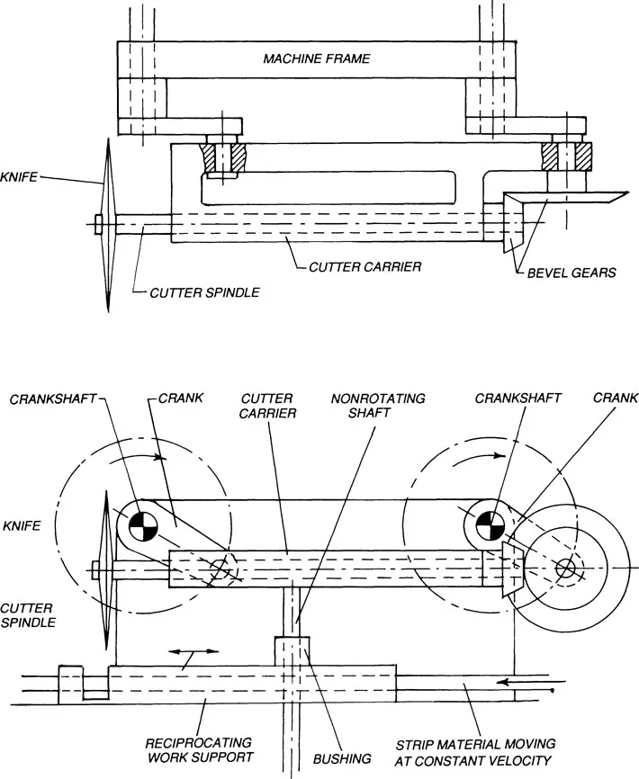
Figure 1.2 Device for cutting material on-the-fly.
Simplified and Improved Cutoff Device for Cans and Cigarettes Using the Turning-Joint Mechanism
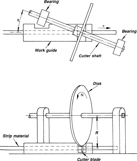
Figure 1.3 Device for cutting material on-the-fly but greatly simplified in comparison with the design in Fig. 1.2.
An improved version of a cutoff mechanism was invented by the author, U.S. Patent #3,183,754. Length of the cutoff piece can be varied using the turning-joint mechanism illustrated in Fig. 1.3. The device consists of a cutter blade attached to a circular disc on a shaft supported by two bearing brackets. The cutter blade is oriented so that when it is in its lowest position, as shown, it is perpendicular to the center line of the material being cut. The strip is supported by a work guide.
Angle α between the center line of the material and that of the cutter shaft can be determined by the equation
or
where R is the active cutting radius of the blade in inches, N is the rotary speed of the disc in rpm, and V is the velocity of the material in inches per second. In order to cut various lengths of strip material at different strip velocities V, the following principle is applied: the knife is rotated with a speed N equal to the number of pieces to be cut per minute. Angle a is then adjusted according to the above equation and the blade angle is reset to cut perpendicular to the moving strip.
The device has been successful in cutting pre-slit tubes for can manufacture at a production rate of 1000–2000 cans per minute. Actual deviation from an exact perpendicular cut is about 0.002 in. for an active cutting radius R of 2.5 in. It is used today in high speed cigarette-making machines, where it cuts cigarettes on-the-fly with a speed of 2000 cigarettes per minute. When two knives on the same disc are employed, the device cuts 4000 cigarettes per minute. The device can be completely dynamically balanced.
Figure 1.4 shows four sliding-joint mechanisms in series, each mechanism in the form of a cylinder and a piston. Due to the series connection of these mechanisms, the stroke of each cylinder is added to the output motion. Cylinder 1 has a stroke of 1 mm, cylinder 2 a stroke of 2 mm, cylinder 3 a stroke of 4 mm, and cylinder 4 a stroke of 8 mm. Because the strokes are all added linearly, the output member can be positioned in any one of 16 position. The mechanism has four degrees of freedom and is an open kinematic chain. If a link mechanism were to be used instead, based on prevailing kinematic literature, the result would be a monster of links and would not even be accurate.
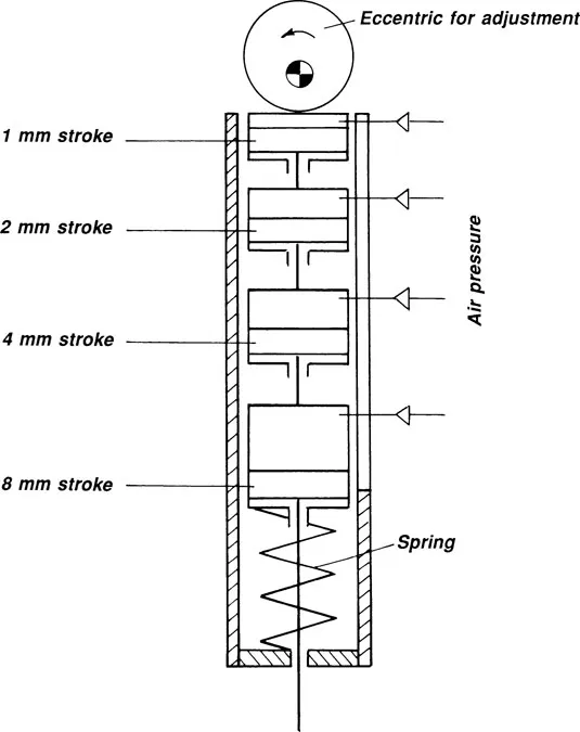
Figure 1.4 Mechanism with four inputs (air pressure). The output member can be positioned in any one of 16 positions.
The Rolling-Joint Mechanism
I have been told that the inventor of the Spirograph drawing toy has earned millions. The spirograph in its simplest form is made of two gears, where one gear is fixed and the other gear is made to roll on the fixed gear by means of a pencil that presses the two gears against each other. The pencil inserted through a hole in the moving gear, at the same time traces a curve.
The position of the pencil on the moving gea...
Inhaltsverzeichnis
- Cover
- Half Title
- Title Page
- Copyright Page
- Table of Contents
- Preface
- 1. Five Basic Mechanisms
- 2. Motion and Force Transmission in Linkages
- 3. The Slider Crank
- 4. Geneva and Star-Wheel Mechanisms
- 5. Planetary Gear Systems
- 6. Cycloidal Mechanisms
- 7. Chain-Driven Mechanisms
- 8. Screw Mechanisms
- 9. Clamping Mechanisms
- 10. Antibacklash Devices
- 11. Infinite-Variable-Speed Drives
- 12. Snap-Action Switching Mechanisms
- 13. Parallelogram Mechanisms
- 14. Gears, Gearing, and Noncircular Gears
- 15. Detent, Indexing, and Ratchet Mechanisms
- 16. Overload and Overrunning Clutches
- 17. Systematic Mechanism Design
- General Bibliography
- Bibliography: Planetary Gear Systems
- Index
Zitierstile für Classical and Modern Mechanisms for Engineers and Inventors
APA 6 Citation
Jensen, P. (2018). Classical and Modern Mechanisms for Engineers and Inventors (1st ed.). CRC Press. Retrieved from https://www.perlego.com/book/1578910/classical-and-modern-mechanisms-for-engineers-and-inventors-pdf (Original work published 2018)
Chicago Citation
Jensen, Preben. (2018) 2018. Classical and Modern Mechanisms for Engineers and Inventors. 1st ed. CRC Press. https://www.perlego.com/book/1578910/classical-and-modern-mechanisms-for-engineers-and-inventors-pdf.
Harvard Citation
Jensen, P. (2018) Classical and Modern Mechanisms for Engineers and Inventors. 1st edn. CRC Press. Available at: https://www.perlego.com/book/1578910/classical-and-modern-mechanisms-for-engineers-and-inventors-pdf (Accessed: 14 October 2022).
MLA 7 Citation
Jensen, Preben. Classical and Modern Mechanisms for Engineers and Inventors. 1st ed. CRC Press, 2018. Web. 14 Oct. 2022.