Physics
Electric Generators
Electric generators are devices that convert mechanical energy into electrical energy through the process of electromagnetic induction. They typically consist of a coil of wire rotating within a magnetic field, which induces a flow of electric current. This process is fundamental to the generation of electricity in power plants and various other applications.
Written by Perlego with AI-assistance
Related key terms
1 of 5
12 Key excerpts on "Electric Generators"
- eBook - ePub
- Pedro Ponce, Arturo Molina, Omar Mata, Luis Ibarra, Brian MacCleery(Authors)
- 2017(Publication Date)
- CRC Press(Publisher)
2Power Flow and Electric Machinery Basics
As a first step into the electric grid, the fundamental topics about power generation, transmission, distribution, and consumption must be established. Each phase must then be first described and appropriately placed among the others so the power flow is thoroughly understood. This chapter aims to introduce the electric grid by presenting how the power flow occurs and by offering the modeling basics around its major electromagnetic components.An electric machine is a device that can convert either mechanical energy to electrical energy or electrical energy to mechanical energy. When such a device is used to convert mechanical energy to electrical energy, it is called a generator. When it converts electrical energy to mechanical energy, it is called a motor. Since any given electric machine can convert power in either direction, any machine can be used as either a generator or a motor. Almost all practical motors and generators convert energy through the interaction of a magnetic field, and only machines using magnetic fields to perform such conversions are considered in this book.Many concepts must be established before performing any analysis of electric machines. The principle of electromechanical energy conversion is the most important law of machine analysis. This theory allows us to establish an expression of electromagnetic torque in terms of machine variables, like the currents and the displacement of the mechanical system. In this chapter, basic principles that will be mentioned are the equivalent circuit representations of magnetically coupled circuits, the concept of a sinusoidally distributed winding, and the winding inductances, among others.2.1 A glance into power flow2.1.1 GeneratorsThe generators produce the electrical energy distributed by a power system. Almost all of the generators in use today produce electrical energy by converting mechanical energy to electrical energy through the action of a magnetic field. The mechanical energy comes from a prime mover, which is the device that spins the generator. Prime movers are usually some form of steam or water turbines, but diesel engines are sometimes used in remote locations. Modern generators generate electrical power at voltages of13.8 - 24 [ k V ] - eBook - PDF
- Michael Brumbach(Author)
- 2016(Publication Date)
- Cengage Learning EMEA(Publisher)
When magnetism is used to produce electricity, it makes no difference whether the conductor moves through the field or the magnetic field moves across the conductor. It is the interaction between the two that develops electrical pressure (emf) (Figure 16–1A and Figure 16–1B). The direction of the emf can be determined by the use of the left-hand rule for a generator. Using the left hand, extend the thumb, index finger, and middle finger so they form right angles to one an-other. When the index finger points in the direction of the magnetic field (from north to south) and the thumb points in the direction of motion of the con-ductor, the middle finger will point in the direction of the induced emf (Figure 16–2). GENERATOR CONSTRUCTION It is frequently stated that a generator is a machine that changes mechanical energy into electrical en-ergy. This statement, although true, is somewhat misleading. A generator actually converts both mechanical and magnetic energy into electrical energy. There are many ways to drive generators. For example, in northeastern United States, many generators are driven by steam turbines. The chemi-cal energy of the fuel is converted into heat energy to make steam. The steam pressure drives the prime mover, which in turn drives the generator rotor. In large generators, the rotor contains the electromag-nets. These magnets are rotated past coiled conduc-tors wound on the stator (the stationary part of the generator). As the magnetic field moves across the stator coils, it induces an emf into them, producing electrical energy. N S FIGURE 16–1A Moving a conductor up through a magnetic field (electromagnetic induction). N FIGURE 16–1B Moving a magnetic field through a coil (electromagnetic induction). FIGURE 16–2 Left-hand rule for a generator. Motion Field Current Copyright 2017 Cengage Learning. All Rights Reserved. May not be copied, scanned, or duplicated, in whole or in part. - eBook - ePub
- Ali Mehrizi-Sani, Turan Gonen(Authors)
- 2024(Publication Date)
- CRC Press(Publisher)
5 Electromechanical Energy Conversion PrinciplesDOI: 10.1201/9781003129745-55.1 Introduction
According to the energy conversion principle, energy is neither created nor destroyed: it is simply changed in form. The role of electromagnetic (or electromechanical) machines is to transmit energy or convert it from one type of energy to another. For example, the transformer transmits electrical energy, changing only the potential difference and current at which it exists. However, it also converts a small amount of electrical energy to heat. This is an unwanted result that is required to be minimized at the design stage.However, a rotational or translational electromagnetic machine converts energy from mechanical to electrical form, or vice versa, that is, it operates as a generator or motor. In the process,1 it also converts some electrical or mechanical energy to unwanted heat. In general, Electric Generators and motors of all kinds can be defined as electromechanical energy converters. Their main components are an electrical system, a mechanical system, and a coupling field, as shown in Figure 5.1 .Figure 5.1A representation of electromechanical energy conversion.5.2 Fundamental Concepts
In this section, some of the basic concepts involving electrical rotating machines are reviewed. Such concepts include angular velocity, angular acceleration, mechanical work, power, and torque.As explained in Chapter 1 , most electrical machines rotate around an axis known as the shaft of the machine. As can be seen in Figures 5.1 and 5.2 , the input of a generator and the output of the motor are mechanical in nature. If the shaft rotates in a counterclockwise (CCW) direction rather than in a clockwise - eBook - ePub
The Electric Power Industry
A Nontechnical Guide
- Thomas O. Miesner, A. Andrew Gallo(Authors)
- 2022(Publication Date)
- PennWell Books(Publisher)
Early in the development of electrical systems, North America adopted one combination of distribution voltage and electrical generation frequency, and Europe developed another. Endless debates ensued trying to prove one was “better” than the other. The truth is each system has its advantages and disadvantages. Once established, it was hard to change, so they continued on. Both follow the same laws of physics and behave largely the same.Electromagnetic Generators
As shown in Figure 3-2 , over 90% of the electricity the world uses today comes from electromagnetic generators that operate on the principle of electrical induction purportedly discovered by Michael Faraday.As already stated several times in this text, electricity and magnetism are directly and causally related. Mr. Faraday discovered that changing the magnetic field around a coil of wire induces an electromagnetic force (emf) in that wire, measured in volts. Magnetic force can be changed by:
A coil is a bundle of wires produced by winding one wire in a circle or other geometric shape. Coils are sometimes generically called windings.Winding vs. Coil- changing the magnetic field strength;
- moving the magnet closer to or farther from the coil;
- moving the coil closer to or farther from the magnet;
- rotating the coil relative to the magnet or the magnet relative to the coil.
The magnet can be either a permanent magnet or an electromagnet.Most generators today rotate the magnet relative to the coil and use electromagnets rather than permanent magnets. Electromagnetic generators consist of three main parts:- Rotor
- Stator
- Exciter
Essentially the opposite of generators, motors have a rotor and stator. In the motor, the current drives the magnetic field making the rotor turn.Electric MotorsNot surprisingly, the rotor rotates, and the stator remains stationary. Either the rotor or the stator produces the magnetic field. The other has conductors – commonly comprised of coils of wire, giving rise to the term coils - eBook - PDF
- John D. Cutnell, Kenneth W. Johnson, David Young, Shane Stadler(Authors)
- 2018(Publication Date)
- Wiley(Publisher)
This statement is a consequence of the law of conservation of energy. 22.7 The Electric Generator In its simplest form, an electric generator consists of a coil of N loops that rotates in a uniform magnetic field B → . The emf produced by this generator is given by Equation 22.4, where A is the area of the coil, is the angular speed (in rad/s) of the coil, and ℰ 0 = NAB is the peak emf. The angular speed in rad/s is related to the frequency f in cycles/s, or Hz, according to = 2f. ℰ = NABω sin ωt = ℰ 0 sin ωt (22.4) When an electric motor is running, it exhibits a generator-like behavior by producing an induced emf, called the back emf. The current I needed to keep the motor running at a constant speed is given by Equation 22.5, where V is the emf applied to the motor by an external source, ℰ is the back emf, and R is the resistance of the motor coil. I = V − ℰ R (22.5) 22.8 Mutual Inductance and Self-Inductance Mutual induction is the effect in which a changing current in the primary coil induces an emf in the secondary coil. The average emf ℰ s induced in the secondary coil by a change in current ΔI p in the primary coil is given by Equation 22.7, where Δt is the time interval during which the change occurs. The con- stant M is the mutual inductance between the two coils and is measured in henries (H). ℰ s = −M ∆ I p ∆ t (22.7) Self-induction is the effect in which a change in current ΔI in a coil in- duces an average emf ℰ in the same coil, according to Equation 22.9. The constant L is the self-inductance, or inductance, of the coil and is measured in henries. ℰ = −L ∆ I ∆ t (22.9) To establish a current I in an inductor, work must be done by an external agent. This work is stored as energy in the inductor, the amount of energy being given by Equation 22.10. The energy stored in an induc- tor can be regarded as being stored in its magnetic field. At any point in air or vacuum or in a nonmagnetic material where a magnetic field B → - No longer available |Learn more
- (Author)
- 2014(Publication Date)
- Academic Studio(Publisher)
________________________ WORLD TECHNOLOGIES ________________________ Chapter 4 Electrostatic Generator and Induction Electrostatic Generator An electrostatic generator , or electrostatic machine , is a mechanical device that produces static electricity , or electricity at high voltage and low continuous current. The knowledge of static electricity dates back to the earliest civilizations, but for millennia it remained merely an interesting and mystifying phenomenon, without a theory to explain its behavior and often confused with magnetism. By the end of the 17th Century, researchers had developed practical means of generating electricity by friction, but the development of electrostatic machines did not begin in earnest until the 18th century, when they became fundamental instruments in the studies about the new science of electricity. Electrostatic generators operate by using manual (or other) power to transform mechanical work into electric energy. They develop electrostatic charges of opposite signs rendered to two conductors, using only electric forces. They work by using moving plates, drums, or belts to carry electric charge to a high potential electrode. The charge is generated by one of two methods: either the triboelectric effect (friction) or electrostatic induction. Description Electrostatic machines are typically used in science classrooms to safely demonstrate electrical forces and high voltage phenomena. The elevated potential differences achieved have been also used for a variety of practical applications, such as operating X-ray tubes, medical applications, sterilization of food, and nuclear physics experiments. Electrostatic generators such as the Van de Graaff generator, and variations as the Pelletron, also find use in physics research. - H. Lee Willis, Lorrin Philipson(Authors)
- 2018(Publication Date)
- CRC Press(Publisher)
If frequency becomes slightly fast, the opposite is done. Beyond that, if the frequency in a particular location starts to deviate from that in the rest of the system, it may mean that there is a failure or some other difficulty with equipment, lines, or a customer appliance, and devices designed to sense this will operate circuit breakers, etc., carefully opening circuits to avoid any possible damage or safety problems. 160 Chapter 6 6.3 TYPES OF GENERATING PLANTS What Turns the Generator? Something must turn the rotor in a generator so that it can produce electric power. The effort required to turn it is not trivial. Power out equals power in . All that the electric generator does is convert mechanical power from whatever is turning it, into electrical power. A human being can turn a very small generator with a hand crank, producing enough power for one or two light bulbs. However, to achieve any significant amount of power, some other source of energy beyond human or animal power must be used to turn the generator. A wide variety of energy sources is utilized for the resulting generation systems. In order of their usage worldwide, these can be divided into three major categories: (1) Fossil fuel powered generation: Coal, oil, natural gas. (2) Nuclear fission powered generation. (3) Renewable powered generation: Wind, solar, hydro, photovoltaic, geothermal, and bio-mass. These types are covered in Chapter 7. Fossil-Fuel Powered Generators The most convenient, economical, and widely used method of producing electric power is to burn a fossil fuel, be it natural gas, coal, peat, fuel oil, diesel fuel, kerosene (paraffin), or refined gasoline, in a suitable machine, using rotating power to spin the electric generator. Except in the case of fuel cells, where no rotation or combustion takes place, this is always accompanied by burning, with its attendant pollution concerns. Generator Turbines Figure 6.5 A turbine generator unit for a large power plant.- M. Godoy Simões, Felix A. Farret(Authors)
- 2014(Publication Date)
- CRC Press(Publisher)
Furthermore, any terrestrial solar conversion system needs to be integrated with either an energy storage system or with another type of conversion system to supply energy when solar energy is not available. This feature limits even more the use of photovoltaic cells in large power schemes. The principle of a rotating electrical generator is based on the relative move-ment between a coil and a magnetic core. If a coil is rotated between a pair of poles (a field) of an electromagnet or a permanent magnet, the output from the rotor will be either alternating or direct current, depending on whether a slip ring (ac) or segmented commutator (dc) is employed. The field windings of a conventional dc generator require a dc power supply, and they can be excited in several ways. Some of these machines must be excited by an external dc power generator. Others are self-excited (shunt, series, or compound), needing only a small amount of residual magnetic flux present in the core of the machine to start the excitation process. AC current generators or alternators also require a dc power supply for the field winding, usually coming from a small dc generator (exciter) connected to the same alternator shaft. These generators can be synchronous or asynchronous; they are synchronous if their frequency is an integer multiple of the frequency of the grid. 5 Principles of Alternative Sources of Energy and Electric Generation When connecting a generator to an ac power grid, care must be taken that the alter-nator is in phase with the alternating current of the grid at the instant of connec-tion. If the alternator is out of phase, the grid will cause immediate acceleration or deceleration of the rotor and high peaks of voltage and current. Severe damage to the machine may result. Asynchronous generators do not suffer so drastically from this limitation, but they may cause stabilization problems to the network, since their power frequency is not a fixed value.- eBook - ePub
- Zeki Uğurata Kocabiyikoğlu(Author)
- 2020(Publication Date)
- CRC Press(Publisher)
3 Principles of Electromechanical Energy Conversion3.1 Introduction
Electromechanical devices convert electrical energy into mechanical energy and vice versa. Energy conversion takes place through the medium of magnetic field. Electromechanical energy conversion is a reversible process except for the losses in the system. We can categorise the electromechanical energy conversion devices in the following manner:- Transducers: These are the first category of devices that involve low-energy conversion signals from electrical to mechanical or vice versa. Microphones, sensors, and loudspeakers are typical examples of this category of devices which operate generally under linear conditions.
- Force-producing devices: These are the second category of devices that consist of force- or torque-producing devices with limited mechanical motion. Examples are solenoids, relays, and electromagnets.
- Continuous energy conversion equipment: Examples are motors and generators that are used for bulk energy conversion and utilisation.
In this chapter, we first discuss transducers and force-producing devices and then continuous energy conversion devices. In doing these, we try to keep as short and as less time consuming as possible to understand the basics of the subject.3.2 Forces and Torques in Magnetic Fields
According to Lorentz’s force law, in pure magnetic field systems, the force on a moving particle of charge q is indicated by the following vector cross product:F = q()v →×B →where v is the velocity in m/s of the particle of charge q moving in a magnetic field density of B Tesla (Figure 3.1 - eBook - PDF
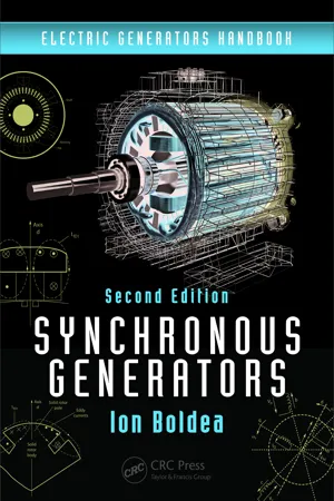
- Ion Boldea(Author)
- 2015(Publication Date)
- CRC Press(Publisher)
We refer to changes in flora and fauna due to hydro-dams intrusion in the natural habitat. Big windmill farms tend to influence the fauna and are also sometimes considered “ugly” to the human eye. Consequently, in forecasting the growth of electric energy consumption on earth, we must consider all these very complex limitation factors. Shifting to more renewable energy sources (wind, hydro, tidal, solar, etc.) while using combined heat-electricity production from fossil fuels to increase the energy conversion factor, together with intelligent energy conservation, could be a complicated, but a potent, way of increasing material prosperity in more harmony with the environment. 1.4 Electric Power Generation Electric energy (power) is produced by coupling a prime mover that converts the mechanical energy (called a turbine) to an electrical generator, which then converts the mechanical energy into electri-cal energy (Figure 1.3). An intermediate form of energy is used for storage in the electrical generator. 5 Electric Energy and Electric Generators This is the so-called magnetic energy stored, mainly between the stator (primary) and the rotor (second-ary). The main types of “turbines” or prime movers are as follows: Steam turbines Gas turbines Hydraulic turbines Wind turbines Diesel engines Internal combustion engines Figure 1.3, which is self-explanatory, illustrates the most commonly used technologies to produce electric energy. They all use a prime mover that outputs mechanical energy. - eBook - PDF
Electrical Principles & Practice NQF4 SB
TVET FIRST
- Jowaheer Consulting and Technologies(Author)
- 2014(Publication Date)
- Macmillan(Publisher)
The two ends of the wire in the coil are connected to two slip rings , A 1 and A 2 . Carbon brushes B 1 and B 2 are used to connect these rotating coils to an external circuit. The movement of the coil in the magnetic field causes a voltage to be induced between the ends of the wires. This voltage or emf changes in size and direction as the coil turns in the magnetic field. The emf can be represented by a sine wave as shown in Figure 5.2. A 0° B 90° C 180° D 270° E 360° S N S N S N S N S N voltage rotation in degrees A B C D E 0° 90° 180° 270° 360° Figure 5.2: Sine wave of emf generated by an alternator Generators normally produce two-way or alternating current. This is why they are often called alternators. To change the alternating current (AC) to direct current (DC), the generator must be fitted with a switching device called a rectifier to keep the current flowing in only one direction. A semiconductor diode is an example of a rectifier . N S B 1 B 2 A 2 A 1 to external circuit e.g. load Figure 5.1: An alternator slip ring: a device that maintains electrical contact between a rotating component, for example, a rotating coil, and a stationary component, for example, the electrical terminals rectifier: an electrical device that converts alternating current to direct current by allowing it to flow in one direction only Words & Terms Did you know? The first alternator to produce alternating current was a dynamo electric generator based on Michael Faraday’s principles. 94 Module 5: The principles behind the generation and supply of electricity Generators are widely used these days due to the frequency of power outages which result from the demand for electricity exceeding the supply. An investment in generators is essential for businesses to survive in these tough economic times. In the workplace Generating single-phase and three-phase AC voltage Single-phase voltage and three-phase voltage are generated in the same way. - eBook - ePub
- Michael E. McCormick(Author)
- 2013(Publication Date)
- Dover Publications(Publisher)
In this chapter, several electromechanical energy conversion systems are discussed. The various methods of transmission and storage are also described.5.1 Basic Electromechanical Energy Conversion Techniques
The eight generic wave energy conversion techniques described in Sections 4.1 and 4.2 (wave focusing is not a conversion technique per se) have one or more possible electromechanical energy conversion techniques associated with them. In this section the two most popular electromechanical systems are described: the mechanical-drive generator and the fluid-drive generator.A Mechanically Excited Generators
Consider the wave energy conversion systems sketched in Figure 5.1 . InFigure 5.1aa heaving float is attached to a line that passes over a pulley connected to a rotating electrical generator and then to a weight. The weight ensures that the line remains in tension. As the float rises the pulley turns in a clockwise direction while the pulley direction is reversed as the float falls. A ratchet device can be used to insure that the generator rotates in only one direction. A variation of this basic system is to replace the weight by a spring-loaded pulley system at the generator, as inFigure 5.1b, where a purely pitching body is sketched using a pully generator device similar to that in Figure 5.1a .Figure 5.1 Basic mechanically excited electrical generation schemes.Figure 5.2 Heaving excited gear-sprocket generator system.Another mechanical-drive system that is often suggested for heaving wave energy converters is the gear system sketched in Figure 5.2 . InFigure 5.2aa heaving circular cylinder is shown attached to a vertical shaft having gears on its right side. These gears mate with a sprocket that, in turn, is attached to the generator shaft. The motions of the cylinder are described by equation (4.12) where, in the case of resonance, the phase angles γ and σz have values of 0 and 90°, respectively. We assume this condition in the analysis that follows; thus at resonance
Index pages curate the most relevant extracts from our library of academic textbooks. They’ve been created using an in-house natural language model (NLM), each adding context and meaning to key research topics.
