Technology & Engineering
Screw Thread
A screw thread is a helical ridge wrapped around a cylinder or cone, used to convert rotational motion into linear motion or vice versa. It is a crucial component in fastening and assembly processes, providing a secure and adjustable connection. Screw threads are found in a wide range of applications, from machinery and construction to everyday items like screws and bolts.
Written by Perlego with AI-assistance
Related key terms
1 of 5
8 Key excerpts on "Screw Thread"
- eBook - PDF
- Rex Miller, Mark Richard Miller(Authors)
- 2005(Publication Date)
- Audel(Publisher)
Chapter 8 Cutting Screw Threads on the Lathe The Screw Thread is a very important mechanical device used for adjusting, fastening, and transmitting motion. Thread-cutting in the engine lathe requires a thorough knowledge of thread-cutting principles and procedures. Screw Thread Systems The threading operation actually involves cutting a helical groove of definite shape or angle, with a uniform advancement for each revolution, either on the surface of a round piece of material, or inside a cylindrical hole. Threads are either right-hand threads (advanced clockwise) or left-hand threads (advanced counterclock-wise). A number of thread systems are in use, which can result in con-fusion for a mechanic or machinist. Therefore, a mechanic or machinist should be familiar with the standard systems and their adaptations. Screw Thread Forms The most-used forms of Screw Threads have symmetrical sides inclined at equal angles with a vertical centerline through the apex of the thread. The Unified, Whitworth , and Acme forms are exam-ples. The Sharp-V was an early form of thread that is now used only occasionally. The symmetrical threads are easy to manufacture and are widely used as general-purpose fasteners. In addition, the so-called translation threads are used to move, or translate, machine parts against heavy loads. Thus, a stronger thread is required. Some of these translation threads that are widely used are the square , Acme , and buttress threads. The square thread is the most efficient of these threads. However, it is the most diffi-cult to cut because of its parallel sides, and it cannot be adjusted to compensate for wear. The Acme thread is only slightly weaker and less efficient, and it has none of the disadvantages of the square thread. The buttress thread is used to translate loads in one direc-tion only. It combines the ease of cutting and adjustment of the Acme thread with the efficiency and strength of the square thread. 167 - eBook - PDF
- Keith L. Richards(Author)
- 2012(Publication Date)
- CRC Press(Publisher)
113 4 Mechanical Fasteners 4.1 THREADED FASTENERS This chapter covers threaded fasteners. These are a very flexible method for attaching components as they allow future easy disassembly. Threaded fasteners are designed principally for tensile loads but will accept a small level of shear load. This chapter begins with a general description of threads and then progresses to cover pre-tension diagrams, and so forth. 4.2 BASIC TYPES OF THREADED FASTENERS Bolt A bolt is a threaded fastener that passes through clearance holes in mating members and is secured with a nut at the end opposite the head of the bolt (Figure 4.1). Screw A screw is a threaded fastener that passes through a clearance hole in one member and into a threaded hole in the other mating member (Figure 4.2). Threaded fasteners are available in a wide variety of head shapes (Figure 4.3), including some of the following. 4.3 THREAD STANDARDS There are several national and international standards covering fastener threads. These include those listed in Table 4.1. 4.4 THREAD PROFILES The pitch line or diameter is located at 0.5 the height of the theoretical sharp v-thread profile (Figure 4.4). 4.5 THREAD SERIES The number of threads per unit length distinguishes groups of diameter-pitch combinations from each other when applied to a specific diameter. ISO Metric Series. Metric system of diameters, pitches, and tolerance/allowances. This sys-tem is now the most common thread system in Europe and many parts of the world. There are two series of metric thread: metric coarse and metric fine. Unified Coarse Thread Series (UNC). Most commonly used in the majority of bolts, screws, and nuts in general engineering applications. This system is most commonly used in the United States and in Europe on old designs not yet converted to metric systems. Unified Fine Thread Series (UNF). This system is used when there is a requirement for a finer pitch of thread, i.e., when the length of thread engagement is restricted. - eBook - ePub
- Peter Childs, Peter R. N. Childs(Authors)
- 2018(Publication Date)
- Butterworth-Heinemann(Publisher)
Table 16.2 .Fig. 16.9 (A) Right hand thread; (B) left hand thread.Fig. 16.10 Specialist terminology used for describing threads.Fig. 16.11 Single, double and triple start screws.Table 16.2 Thread terminologyTerm Description Pitch The thread pitch is the distance between corresponding points on adjacent threads. Measurements must be made parallel to the thread axis Outside diameter The outside or major diameter is the diameter over the crests of the thread measured at right angles to the thread axis Crest The crest is the most prominent part of thread; either external or internal Root The root lies at the bottom of the groove between two adjacent threads Flank The flank of a thread is the straight side of the thread between the root and the crest Root diameter The root, minor or core diameter is the smallest diameter of the thread measured at right angles to the thread axis Effective diameter The effective diameter is the diameter on which the width of the spaces is equal to the width of the threads. It is measured at right angles to the thread axis Lead The lead of a thread is the axial movement of the screw in one revolution. Lead and pitch are the same for single start screws, but different for double or multiple start screws (Fig. 16.11 ) Thread forms, angle of helix and so on, vary according to specific standards. Common standards developed include UNS (unified national standard series threads) and ISO threads. Both of these use a 60° included angle but are not interchangeable. The form for an ISO metric thread for a nut is illustrated in Fig. 16.12 . In practice the root of the nut and the crest of the mating bolt are rounded. Both male and female ISO threads are subject to manufacturing tolerances, which are detailed in BS 3643. A coarse series thread and fine series threads are defined in the ISO standard but fine series threads tend to be more expensive and may not be readily available from all stockists. Table 16.3 - eBook - ePub
- Marcus Bowman(Author)
- 2015(Publication Date)
- Crowood(Publisher)
Fig. 2.12 shows the cylinder whose surface is aligned with the tops of the thread, which represents the ‘major diameter’ of the thread. Fig. 2.13 shows a shaft surface aligned with the bottom of the groove, so that the groove as well as the projection stand above the surface of the shaft. That represents the ‘minor diameter’ of the thread.Although the major diameter and the pitch give an indication of the overall size, it is only by measuring and controlling the pitch diameter that we can be sure of producing a thread which has a particular quality of fit with a standard nut, screw or threaded hole.Threaded shafts and their matching threaded holes are so commonly used as fasteners to hold other parts together that the threaded shaft is termed a ‘screw’, and where the threaded hole is a separate individual part it is called a ‘nut’.Fig. 2.14: A stud is a length of shaft threaded at both ends and with a plain unthreaded section in between.Fig. 2.15: Some nuts have integral flanges to spread the load when the nut is used to squeeze a component against the underside of the head of a mating screw.A screw normally has a head which can be gripped and turned to insert or retract, tighten or loosen the screw. A headless screw, usually a portion of rod threaded at both ends and with an unthreaded section in between, is called a ‘stud’ (Fig. 2.14 ). A screw usually has an integral head which provides a flange and is shaped to allow it to be gripped and turned, while the nut containing the hole has some material around the outside which is shaped so that it, too, can be gripped and turned. The nut also acts as a flange, so that other parts can be squeezed between the flanges on the screw and the nut. In cases where a larger flange is needed to spread the load, the nut may have a larger integral flange (Fig. 2.15 ).SCREW, BOLT, NUT AND HOLE Opinions vary, as does the use of the terms associated with screws, nuts, bolts and threaded. In this book we use the following terms: - eBook - ePub
- Ansel C. Ugural(Author)
- 2020(Publication Date)
- CRC Press(Publisher)
shank or bolt length. Also, observe the washer face, the fillet under the bolt head, and the start of the threads. Referring to the figure, some terms from geometry that relate to Screw Threads are defined as follows.FIGURE 15.2 Hexagonal bolt and nut illustrate the terminology of threaded fasteners. Notes : P , the pitch; λ, the helix or lead angle; α, the thread angle; d , the major diameter; d p , the pitch diameter; d r , the root diameter; and L n , the nut length.Pitch p is the axial distance measured from a point on one thread to the corresponding point on the adjacent thread. Lead L represents the axial distance that a nut moves, or advances, for one revolution of the screw. Helix angle λ , also called the lead angle, may be cut either right-handed (as in Figure 15.2 ) or left-handed. All threads are assumed to be right-handed, unless otherwise stated.A single-threaded screw is made by cutting a single helical groove on the cylinder. For a single thread , the lead is the same as the pitch. Should a second thread be cut in the space between the grooves of the first (imagine two strings wound side-by-side around a pencil), a double-threaded screw would be formed. For a multiple (two or most)-threaded screw ,
whereL = n p(15.1) L = the leadn = the number of threadsp = the pitchWe observe from this relationship that a multiple-threaded screw advances a nut more rapidly than a single-threaded screw of the same pitch. Most bolts and screws have a single thread, but worms and power screws sometimes have multiple threads. Some automotive power-steering screws occasionally use quintuple threads.15.2.1 Unified and ISO Thread Form
For fasteners, the standard geometry of Screw Thread shown in Figure 15.3 is used. This is essentially the same for both the Unified National Standard (UNS), or the so-called unified, and International Standards Organization (ISO) threads. The UNS (inch series) and ISO (metric series) threads are not interchangeable. In both systems, the thread angle is 60°, and the crests and roots of the thread may be either flat (as depicted in the figure) or rounded. The major diameter d and root (minor) diameter d r refer to the largest and smallest diameters, respectively. The diameter of an imaginary cylinder, coaxial with the screw, intersecting the thread at the height that makes width of thread equal to the width of space, is called the pitch diameter d p - Toshimichi Fukuoka(Author)
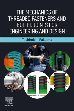
- 2022(Publication Date)
- Elsevier(Publisher)
The jointed portions fastened by use of Screw Threads are generally called a bolted joint. In this book, therefore, the components clamped by various kinds of threaded fasteners are referred to as bolted joints. Basic forms and the usages of Screw Threads have been fundamentally unchanged since the Industrial Revolution. Nevertheless, threaded fasteners and bolted joints have continuously been important research objects in the mechanical engineering field. The biggest reason is that the external loads exerted on bolted joints are continuously being increased!1.2: Geometry and application purposes of Screw Threads
Screw Threads are roughly classified into two types, which are used for clamping and movement transmission, respectively. Most threaded fasteners such as bolts and nuts are basically used for clamping a number of parts composing machines and structures. On the other hand, Screw Threads used for movement transmission deliver various movements by utilizing their helical shape. They are further categorized into two types. One is used for generating large forces by making use of the action of the thread as an inclined plane, e.g., a jack for lifting heavy parts; the other facilitates the conversion between linear and rotational motions, e.g., feed screws built into machine tools. As a similar example, a micrometer provides a dimensional accuracy of 10 μm, in which a large rotation angle is converted into a small linear movement. A certain type of micrometer equipped with a digital display device provides higher accuracy of 1 μm.Fig. 1.1 shows Screw Threads of various forms. Triangular Screw Threads are the most commonly used when clamping multiple parts. On the other hand, trapezoidal Screw Threads are used for motion and power transmission. These types of Screw Threads are often called power screws [17] . The relationship between thread form and application purpose is explained in detail in section 3.2.4- eBook - ePub
- Ansel C. Ugural(Author)
- 2022(Publication Date)
- CRC Press(Publisher)
shank or bolt length. Also, observe the washer face, the fillet under the bolt head, and the start of the threads. Referring to the figure, some terms from geometry that relate to Screw Threads are defined as follows.FIGURE 15.2 Hexagonal bolt and nut illustrate the terminology of threaded fasteners. Notes: P, the pitch; λ, the helix or lead angle; α, the thread angle; d, the major diameter; dp , the pitch diameter; dr , the root diameter; and Ln , the nut length.Pitch p is the axial distance measured from a point on one thread to the corresponding point on the adjacent thread. Lead L represents the axial distance that a nut moves, or advances, for one revolution of the screw. Helix angle λ, also called the lead angle, may be cut either right-handed (as in Figure 15.2 ) or left-handed. All threads are assumed to be right-handed, unless otherwise stated.A single-threaded screw is made by cutting a single helical groove on the cylinder. For a single thread, the lead is the same as the pitch. Should a second thread be cut in the space between the grooves of the first (imagine two strings wound side-by-side around a pencil), a double-threaded screw would be formed. For a multiple (two or most)-threaded screw,whereL = n p(15.1)- L = the lead
- n = the number of threads
- p = the pitch
We observe from this relationship that a multiple-threaded screw advances a nut more rapidly than a single-threaded screw of the same pitch. Most bolts and screws have a single thread, but worms and power screws sometimes have multiple threads. Some automotive power-steering screws occasionally use quintuple threads.15.2.1 UNIFIED AND ISO THREAD FORM
For fasteners, the standard geometry of Screw Thread shown in Figure 15.3 is used. This is essentially the same for both the Unified National Standard (UNS), or the so-called unified, and International Standards Organization (ISO) threads. The UNS (inch series) and ISO (metric series) threads are not interchangeable. In both systems, the thread angle is 60°, and the crests and roots of the thread may be either flat (as depicted in the figure) or rounded. The major diameter d and root (minor) diameter dr refer to the largest and smallest diameters, respectively. The diameter of an imaginary cylinder, coaxial with the screw, intersecting the thread at the height that makes width of thread equal to the width of space, is called the pitch diameter dp - eBook - ePub
Design of Mechanical Elements
A Concise Introduction to Mechanical Design Considerations and Calculations
- Bart Raeymaekers(Author)
- 2022(Publication Date)
- Wiley(Publisher)
8 Bolted Joints8.1 Introduction
In this chapter, we will use the knowledge of the chapters on design for static and dynamic strength and apply it to the design of bolted joints. Bolted joints are connections between mechanical elements that we can assemble and disassemble in a nondestructive manner, using Screw Thread. This contrasts, e.g. welded joints, which once assembled, require destructive methods to disassemble.We first recognize that to understand bolted joints, we must understand Screw Thread. Two categories of Screw Thread exist; Screw Thread that is intended to create motion between two mechanical elements and Screw Thread that is meant to fasten mechanical elements together. We refer to the former category as power screws (sometimes also referred to as lead screws or translation screws), and to the latter category as fasteners.8.2 Power Screws
Power screws are a category of Screw Thread specifically designed to facilitate motion between mechanical elements. It is most often used to convert a rotary into a linear motion to displace a load. For instance, a car jack, a vise, or a lathe are examples of devices that use a power screw to convert rotary into linear motion and to displace a load.8.2.1 Screw Thread Nomenclature and Geometry
Figure 8.1 illustrates the geometry of two common types of Screw Thread used in power screws. Figure 8.1 a shows square Screw Thread, whereas Figure 8.1 b shows trapezoidal Screw Thread, sometimes also referred to as ACME thread. Square Screw Thread offers the lowest friction force between the threaded rod and nut and, thus, is the most energy efficient to convert rotary to linear motion and displace a load. However, it is difficult and expensive to manufacture because of its angle. In contrast, trapezoidal Screw Thread is characterized by a
Index pages curate the most relevant extracts from our library of academic textbooks. They’ve been created using an in-house natural language model (NLM), each adding context and meaning to key research topics.
