Physics
Op Amp
An operational amplifier (op amp) is an electronic component that amplifies the difference in voltage between its two input terminals. It is commonly used in electronic circuits for signal processing, filtering, and mathematical operations. Op amps have high input impedance, low output impedance, and can provide high gain, making them versatile components in physics and engineering applications.
Written by Perlego with AI-assistance
Related key terms
1 of 5
11 Key excerpts on "Op Amp"
 eBook - ePub
- Beijia Ning(Author)
- 2018(Publication Date)
- De Gruyter(Publisher)
5 Operational amplifiers and their applications 5.1 Overview An operational amplifier, usually abbreviated to op-amp or opamp, is a DC-coupled high-gain electronic voltage amplifier with a differential input and, normally, a single-ended output. Under this configuration, an op-amp generates an output voltage, typically hundreds of thousands of times larger than the voltage difference between its two input terminals. Operational amplifiers had their original application in analog computers for many linear and nonlinear mathematical operations [ 13 ]. The versatility of the op-amp is the reason for its popularity in analog circuits as a building block. With the help of negative feedback, the characteristics of an op-amp circuit, such as gain, bandwidth, input impedance, output impedance and so on, are manipulated by external components and have almost nothing to do with temperature change or manufacturing variations [ 12 ]. Packaged as components or used as elements of more complex integrated circuits, op-amps are one of the most widely used electronic devices today, especially in the field of analog circuits, for a wide range of applications in industrial, scientific and consumer devices. Many standard IC op-amps cost only a few cents; while some integrated or hybrid operational amplifiers with special functions may cost over US$ 100 [ 12 ]. Moreover, the op-amp is one type of differential amplifier. Other types of differential amplifier include the fully differential amplifier, the instrumentation amplifier, the isolation amplifier and the negative-feedback amplifier. However, some of these are beyond the coverage of the textbook. Briefly, the following is the historical timeline of the op-amps [ 12, 21 ]. In the 1940s, an op-amp was first invented as a “summing amplifier” by Swartzel of Bell Labs in 1941. Throughout World War II, this invention demonstrated its value, which would have been impossible for other devices eBook - PDF
Fundamentals of Electronics
Book 1 Electronic Devices and Circuit Applications
- Thomas F. Schubert, Ernest M. Kim(Authors)
- 2022(Publication Date)
- Springer(Publisher)
1 C H A P T E R 1 Operational Amplifiers and Applications e Operational Amplifier (commonly referred to as the OpAmp) is one of the primary active devices used to design low and intermediate frequency analog electronic circuitry: its importance is surpassed only by the transistor. OpAmps have gained wide acceptance as electronic building blocks that are useful, predictable, and economical. Understanding OpAmp operation is funda- mental to the study of electronics. e name, operational amplifier, is derived from the ease with which this fundamental building block can be configured, with the addition of minimal external circuitry, to perform a wide variety of linear and non-linear circuit functions. Originally implemented with vacuum tubes and now as small, transistorized integrated circuits, OpAmps can be found in applications such as: signal processors (filters, limiters, synthesizers, etc.), communication circuits (oscillators, modulators, demodulators, phase-locked loops, etc.), Analog/Digital converters (both A to D and D to A), and circuitry performing a variety of mathematical operations (multipliers, dividers, adders, etc.). e study of OpAmps as circuit building blocks is an excellent starting point in the study of electronics. e art of electronics circuit and system design and analysis is founded on circuit realizations created by interfacing building block elements that have specific terminal character- istics. OpAmps, with near-ideal behavior and electrically good interconnection properties, are relatively simple to describe as circuit building blocks. Circuit building blocks, such as the OpAmp, are primarily described by their terminal char- acteristics. Often this level of modeling complexity is sufficient and appropriately uncomplicated for electronic circuit design and analysis. However, it is often necessary to increase the complexity of the model to simplify the analysis and design procedures. No longer available |Learn more
- (Author)
- 2014(Publication Date)
- University Publications(Publisher)
____________________ WORLD TECHNOLOGIES ____________________ Chapter- 1 Operational Amplifier A Signetics μa741 operational amplifier, one of the most successful op -amps. An operational amplifier (op-amp) is a DC-coupled high-gain electronic voltage amplifier with a differential input and, usually, a single -ended output. An op-amp produces an output voltage that is typically hundreds of thousands times larger than the voltage difference between its input terminals. Operational amplifiers are important building blocks for a wide range of electronic circuits. They had their origins in analog computers where th ey were used in many linear, non-linear and frequency-dependent circuits. Their popularity in circuit design largely stems from the fact the characteristics of the final elements (such as their gain) are set by external components with little dependence on temperature changes and manufacturing variations in the op-amp itself. ____________________ WORLD TECHNOLOGIES ____________________ Op-amps are among the most widely used electronic devices today, being used in a vast array of consumer, industrial, and scientific devices. Many standard IC op -amps cost only a few cents in moderate production volume; however some integrated or hybrid operational amplifiers with special performance specifications may cost over $100 US in small quantities. Op-amps may be packaged as components, or used as elements of more complex integrated circuits. The op-amp is one type of differential amplifier. Other types of differential amplifier include the fully differential amplifier (similar to the op-amp, but with two outputs), the instrumentation amplifier (usually built from three op-amps), the isolation amplifier (similar to the instrumentation amplifier, but with tolerance to common -mode voltages that would destroy an ordinary op-amp), and negative feedback amplifier (usually built from one or more op-amps and a resistive feedback network). No longer available |Learn more
- (Author)
- 2014(Publication Date)
- Research World(Publisher)
________________________ WORLD TECHNOLOGIES ________________________ Chapter 4 Operational Amplifier A Signetics μa741 operational amplifier, one of the most successful op -amps. An operational amplifier (op-amp) is a DC-coupled high-gain electronic voltage amplifier with a differential input and, usually, a single-ended output. An op-amp pro-duces an output voltage that is typically hundreds of thousands times larger than the voltage difference between its input terminals. ________________________ WORLD TECHNOLOGIES ________________________ Operational amplifiers are important building blocks for a wide range of electronic circuits. They had their origins in analog computers where they were used in many linear, non-linear and frequency-dependent circuits. Their popularity in circuit design largely stems from the fact that characteristics of the final elements (such as their gain) are set by external components with little dependence on temperature changes and manufacturing variations in the op-amp itself. Op-amps are among the most widely used electronic devices today, being used in a vast array of consumer, industrial, and scientific devices. Many standard IC op-amps cost only a few cents in moderate production volume; however some integrated or hybrid operational amplifiers with special performance specifications may cost over $100 US in small quantities. Op-amps may be packaged as components, or used as elements of more complex integrated circuits. The op-amp is one type of differential amplifier. Other types of differential amplifier include the fully differential amplifier (similar to the op-amp, but with two outputs), the instrumentation amplifier (usually built from three op-amps), the isolation amplifier (similar to the instrumentation amplifier, but with tolerance to common-mode voltages that would destroy an ordinary op-amp), and negative feedback amplifier (usually built from one or more op-amps and a resistive feedback network). No longer available |Learn more
- (Author)
- 2014(Publication Date)
- Academic Studio(Publisher)
____________________ WORLD TECHNOLOGIES ____________________ Chapter- 10 Operational Amplifier A Signetics μa741 operational amplifier, one of the most successful op -amps. An operational amplifier (op-amp) is a DC-coupled high-gain electronic voltage amplifier with a differential input and, usually, a single-ended output. An op-amp produces an output voltage that is typically hundreds of thousands times larger than the voltage difference between its input terminals. Operational amplifiers are important building blocks for a wide range of electronic circuits. They had their origins in analog computers where they were used in many linear, non-linear and frequency-dependent circuits. Their popularity in circuit design largely stems from the fact the characteristics of the final elements (such as their gain) are set by external components with little dependence on temperature changes and manufacturing variations in the op-amp itself. ____________________ WORLD TECHNOLOGIES ____________________ Op-amps are among the most widely used electronic devices today, being used in a vast array of consumer, industrial, and scientific devices. Many standard IC op-amps cost only a few cents in moderate production volume; however some integrated or hybrid operational amplifiers with special performance specifications may cost over $100 US in small quantities. Op-amps may be packaged as components, or used as elements of more complex integrated circuits. The op-amp is one type of differential amplifier. Other types of differential amplifier include the fully differential amplifier (similar to the op-amp, but with two outputs), the instrumentation amplifier (usually built from three op-amps), the isolation amplifier (similar to the instrumentation amplifier, but with tolerance to common-mode voltages that would destroy an ordinary op-amp), and negative feedback amplifier (usually built from one or more op-amps and a resistive feedback network).
- J. David Irwin, David V. Kerns, Jr.(Authors)
- 2022(Publication Date)
- Wiley(Publisher)
CHAPTER 10 Operational Amplifiers and Applications LEARNING OBJECTIVES • To understand the characteristics of operational amplifiers and differential amplifiers • To understand the operation of the ideal op-amp model • To be able to recognize and analyze fundamental op-amp circuits • To understand the application of op-amps in the development of low-pass, high-pass, and bandpass filters • To be able to understand the use of op-amps to construct differentiator and integrator circuits • To understand multistage amplifier circuits • To be able to use op-amps in instrumentation and laboratory measurements and in industrial applications. INTRODUCTION The operational amplifier, or Op Amp as it is commonly known, is a fundamental component in analog electronic systems. Although it can be used in a variety of applications, it is widely used in instrumentation and measurement systems. An actual circuit diagram for a commercial Op Amp is the 741 Op Amp shown in Figure 10.1. Also shown in the figure are the pin connections for a dual in-line package, or DIP, which sup- ports its connection with other electronic components. Even a cursory examination of the circuit schematic for the Op Amp indicates that this is not a trivial network. It is typically constructed as an integrated circuit and may be purchased as a single device, in a DIP that contains several Op Amps or in a “surface mount” package. These elements are not only powerful devices in analog circuit design but are also inexpensive – less than a dollar for a chip in a package. Even after wading through the chapters in this book and developing a knowledge of transis- tors and their applications, the circuit diagram in Figure 10.1 may appear formidable. However, as sophisticated as it appears, it is really nothing more than a high-quality linear voltage ampli- fier. The details of how this circuit is designed are beyond the scope of this book, but follows basic principles described here.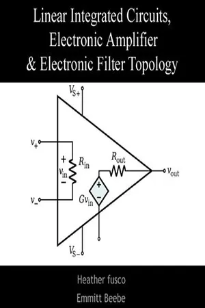 No longer available |Learn more
- (Author)
- 2014(Publication Date)
- College Publishing House(Publisher)
____________________ WORLD TECHNOLOGIES ____________________ Chapter 10 Operational Amplifier A Signetics μa741 operational amplifier, one of the most successful op-amps An Operational amplifier (op-amp) is a DC-coupled high-gain electronic voltage amplifier with a differential input and, usually, a single-ended output. An op-amp produces an output voltage that is typically hundreds of thousands times larger than the voltage difference between its input terminals. Operational amplifiers are important building blocks for a wide range of electronic circuits. They had their origins in analog computers where they were used in many linear, non-linear and frequency-dependent circuits. Their popularity in circuit design largely stems from the fact the characteristics of the final elements (such as their gain) are set by external components with little dependence on temperature changes and manufacturing variations in the op-amp itself. ____________________ WORLD TECHNOLOGIES ____________________ Op-amps are among the most widely used electronic devices today, being used in a vast array of consumer, industrial, and scientific devices. Many standard IC op-amps cost only a few cents in moderate production volume; however some integrated or hybrid operational amplifiers with special performance specifications may cost over $100 US in small quantities. Op-amps may be packaged as components, or used as elements of more complex integrated circuits. The op-amp is one type of differential amplifier. Other types of differential amplifier include the fully differential amplifier (similar to the op-amp, but with two outputs), the instrumentation amplifier (usually built from three op-amps), the isolation amplifier (similar to the instrumentation amplifier, but with tolerance to common-mode voltages that would destroy an ordinary op-amp), and negative feedback amplifier (usually built from one or more op-amps and a resistive feedback network). eBook - PDF
- Jiri Dostal(Author)
- 2013(Publication Date)
- Newnes(Publisher)
Parti The Operational Amplifier This page intentionally left blank 1. Basic Concepts 1.1 The Operational Amplifier The operational amplifier is a versatile amplifying device, originally intended for use in analog computers to perform linear mathematical operations. Forty years of development of the operational amplifier's internal circuit design reflects, to a significant extent, the development of electronic components from vacuum tubes to monolithic integrated circuits. An increasing refinement of the operational amplifier's properties has shifted the emphasis of its ap-plications from laboratories to industry. Due to its high performance, ver-satility, and low price, the operational amplifier now dominates the field of analog electronic systems. We generally define the operational amplifier as a direct-coupled amplifier with a high gain and a low level of inherent noise, capable of stable operation in a closed-feedback loop. The exact meaning of these characteristics will be given in Chapters 2 and 11. It should be mentioned here that the term direct-coupled does not imply an upper limitation of the amplifier's frequency re-sponse but, on the contrary, an extension of the operating range to zero frequency, or infinitely long periods. The direction of signal flow from input to output in an operational amplifier is given by the triangular shape of its symbol in Figure 1-la. Three of the four illustrated terminals represent the three signal terminals of an actual operational amplifier. These are the inverting input, noninverting input, and output. The fourth signal terminal, the ground, may be either actual (Figure 1—lb) or only virtual (power supply common in Figure 1-lc). In either case, it represents symbolically a group of at least two terminals intended for the supply of energy. eBook - PDF
- J. David Irwin, R. Mark Nelms(Authors)
- 2021(Publication Date)
- Wiley(Publisher)
120 CHAPTER 4 4.1 Introduction It can be argued that the operational amplifier, or op-amp as it is commonly known, is the single most important integrated circuit for analog circuit design. It is a versatile intercon- nection of transistors and resistors that vastly expands our capabilities in circuit design, from engine control systems to cellular phones. Early op-amps were built of vacuum tubes, making them bulky and power hungry. The invention of the transistor at Bell Labs in 1947 allowed engineers to create op-amps that were much smaller and more efficient. Still, the op-amp itself consisted of individual transistors and resistors interconnected on a printed circuit board (PCB). When the manufacturing process for integrated circuits (ICs) was developed around 1970, engineers could finally put all of the op-amp transistors and resistors onto a single IC chip. Today, it is common to find as many as four high-quality op-amps on a single IC for as little as $0.40. A sample of commercial op-amps is shown in Fig. 4.1. (a) (b) FIGURE 4.1 A selection of op-amps. On the left (a) is a discrete op-amp assembled on a printed circuit board (PCB). On the right, top-down, a LM324 DIP, LMC6492 DIP, and MAX4240 in a SO-5 package (small outline/5 pins). The Apex Microtechnology PA03 with its lid removed (b) showing individual transistors and resistors. (Left, Courtesy of Mark Nelms and Jo Ann Loden; right, Courtesy of Apex Microtechnology Corp.) Operational Amplifiers LEARNING OBJECTIVES The learning goals for this chapter are that students should be able to: • Apply the model of the op-amp device to determine the currents and voltages in a circuit. • Analyze a variety of circuits that employ op-amps. • Use the model of the op-amp in a number of practical applications to determine the output voltage and/or current with respect to the input voltage(s) and current(s).
- Dennis L. Eggleston(Author)
- 2011(Publication Date)
- Cambridge University Press(Publisher)
6 Operational amplifiers 6.1 Introduction We now turn to an examination of the properties and uses of the operational amplifier or op-amp . A detailed analysis of this multi-stage amplifier circuit is beyond the scope of this text, so we will treat it as a black box device as we did earlier with the voltage regulator. Thus, to use the device, we need only learn and apply some simple rules and, later, the real-world limitations of the device. In current usage, the operational amplifier is usually packaged as an integrated circuit with multiple leads or pins. While there are hundreds of different op-amps with different specifications, they all follow the same usage rules. To be specific, we will focus on a “classic” version: the 741 op-amp. The circuit symbol for the op-amp is shown in Fig. 6.1 . There are inputs for two power supply voltages (one positive and one negative relative to ground, labeled V + cc and V − cc , respectively). There are also two signal inputs: the inverting input , labeled with a minus sign, and the non-inverting input , labeled with a plus sign. Happily, there is only one output. As we know, voltages are always between two points, but our description of the op-amp inputs seems to refer to voltages at one point, the various input pins. It is thus important to note that all of the voltages for the op-amp are referenced to ground (i.e., the second point is ground). While it is common for writers discussing op-amp circuits to refer to the voltage at some point, one should keep in mind that they are really talking about the voltage between this point and ground. Also, the power supply connections shown in Fig. 6.1 are often omitted from circuit diagrams for simplicity, and it is easy for the novice building such a circuit to forget these connections. Of course, the circuit will not work without them. The basic operation of the op-amp can be simply stated. eBook - PDF
- Behzad Razavi(Author)
- 2021(Publication Date)
- Wiley(Publisher)
8 Operational Amplifier as a Black Box Watch Companion YouTube Videos: Razavi Electronics 1, Lec 42: Op Amp Circuits I https://www.youtube.com/watch?v=WzdmaSUCQGM Razavi Electronics 1, Lec 43: Op Amp Circuits II https://www.youtube.com/watch?v=oWMBjDfRacc Razavi Electronics 1, Lec 44: Nonlinear Op Amp Circuits, Op Amp Nonidealities I https://www.youtube.com/watch?v=FWBVjEgPx0U Razavi Electronics 1, Lec 45: Op Amp Nonidealities II https://www.youtube.com/watch?v=VN8SeVA8LnU The term “operational amplifier” (Op Amp) was coined in the 1940s, well before the inven- tion of the transistor and the integrated circuit. Op Amps realized by vacuum tubes 1 served as the core of electronic “integrators,” “differentiators,” etc., thus forming systems whose behavior followed a given differential equation. Called “analog computers,” such circuits were used to study the stability of differential equations that arose in fields such as control or power systems. Since each Op Amp implemented a mathematical operation (e.g., inte- gration), the term “operational amplifier” was born. Op Amps find wide application in today’s discrete and integrated electronics. In the cellphone studied in Chapter 1, for example, integrated Op Amps serve as building blocks in (active) filters. Similarly, the analog-to-digital converter(s) used in digital cameras often employ Op Amps. In this chapter, we study the operational amplifier as a black box, developing op-amp-based circuits that perform interesting and useful functions. The outline is shown below. 1 Vacuum tubes were amplifying devices consisting of a filament that released electrons, a plate that collected them, and another that controlled the flow—somewhat similar to MOSFETs. 355
Index pages curate the most relevant extracts from our library of academic textbooks. They’ve been created using an in-house natural language model (NLM), each adding context and meaning to key research topics.