Physics
Electromechanical Actuators
Electromechanical actuators are devices that convert electrical energy into mechanical motion. They are commonly used in various applications such as robotics, aerospace systems, and industrial machinery. These actuators typically consist of an electric motor, a transmission system, and a mechanism to convert rotary motion into linear motion, allowing for precise control and movement.
Written by Perlego with AI-assistance
10 Key excerpts on "Electromechanical Actuators"
- eBook - ePub
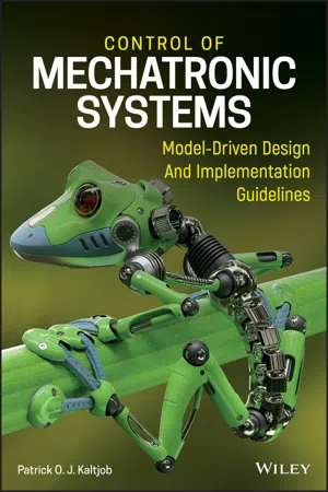
Control of Mechatronic Systems
Model-Driven Design and Implementation Guidelines
- Patrick O. J. Kaltjob(Author)
- 2020(Publication Date)
- Wiley(Publisher)
In this chapter, classical models of electrical-driven actuating systems, along with the dynamics of their associated transmission element dynamics, are presented. Some process models involving various transmission elements are described, in order to illustrate their real-life applications. In addition to electrical-driven actuator characterization, sensor types and measuring principles are covered. Dynamic characterizations are presented for various physical system variables such as linear and rotational position, speed, acceleration, force, torque, chemical content, distance, flow, temperature, proximity, level, and pressure. In addition, signal conditioning principles and categorization (zero-, first-, second-order sensors, etc.), sensor and detector design specifications, and device characteristics such as linearity, sensitivity, limitations, calibration, and saturation are detailed. Finally, the sensing and operating principles of dynamic sensors such as the dynamics model, time domain, and frequency response characteristics are developed.8.2 Actuators in Mechatronics
Electric actuators can generate either a binary output signal (i.e. contact relay) or continuous signal (stepper motor). Such electrical-driven actuating systems can be classified based on their electrostatic or electromagnetic – and even electrothermal – design principles. Their coupled transmission elements generate force to motion, pressure to flow, heat, and so on. Recent advances in nanotechnologies have led to the development of low-scale actuators (nano or micro).Electromechanical Actuators usually operate based on the electrostatic (electrostatic actuators) or the electromagnetic (electromagnetic actuators) principle. Electrostatic actuators use charged particle motion within the induced field to generate adequate force, vibration, pressure, and temperature variation displacement of a membrane or beam. They include piezo-electric actuators, which deliver strain-based actuation from piezo-materials by generating a voltage proportional to the applied mechanical deformation. Such piezo-materials use either ceramics (i.e. lead-zirconate-titanate) or polymers (i.e. polyvinylidene fluoride). Surrounded by electrodes or attached to them they allow strain-based actuation of up to a few kilovolts per millimeter. Among micro-device applications are: (i) position systems, such as micromanipulation (microrobot with piezo-legs), vibration oscillation suppression systems, valves (micro-pumps in artificial hearts), and ultrasonic motors; and (ii) handling systems, such as microgrippers and laser printers (which use charged particles from the toner, which move based on the electrophotographic principle). - eBook - ePub
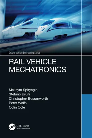
- Maksym Spiryagin, Stefano Bruni, Christopher Bosomworth, Peter Wolfs, Colin Cole(Authors)
- 2021(Publication Date)
- CRC Press(Publisher)
In general, an electro-mechanic actuator consists of an electric motor and of a mechanical transmission providing the interface of the motor to the plant. The electric motor is controlled using a feedback control loop in which the controlled variable can be either a force or a measured displacement/rotation representative of the system's position. A controlled electric motor is termed a servomotor. Recent developments of power electronics have made the control of servomotors much simpler than previously, removing some of the limitations associated with the different typologies of electric motors. Electro-mechanical actuators are typically composed by a servomotor coupled to a mechanical transmission which provides a suitable interface of the servomotor to the plant. In particular, the mechanical transmission may include: A ball screw and nut device to convert the rotation of the output shaft of the servomotor into a linear movement. A gear train to amplify the torque generated by the servomotor by means of a suitable gear ratio. Advantages of electro-mechanical actuators are the compact design with high force density, accurate and fast actuation, high efficiency, no risk of fluid leakage/contamination which is otherwise possible for hydraulic actuators. However, Electromechanical Actuators also have significant drawbacks, namely: risk of jamming due to failures in the mechanical transmission, relatively high cost, high stiffness at high frequency - eBook - PDF
Mechatronics: Designing Intelligent Machines Volume 1
Perception, Cognition and Execution
- George Rzevski(Author)
- 2014(Publication Date)
- Newnes(Publisher)
Electrochemical actuators These are based on electrically excited chemical reactions which transform chemical into kinetic energy, usually within a gas. Applications are limited by the slowness of the reaction and the low power developed. However, the technology uses low voltages and is free of mechanical wear, so it might be of use in medical applications. Electroviscous fluids As with piezoelectric actuators, the technology of electroviscous (or electror-heological) liquids is unlikely to provide primary movements in mechatronics. These fluids are oils with suspended micrometre-sized particles and have high dielectric constants. Their drag characteristics (i.e. viscosity) change when an electric potential is applied, making them suitable for use in clutch mechanisms. Monkman (1993) describes a possible application. The significance of the effect is that it may enable the development of flexibly compliant movement. Actuation can be the weak link in a mechatronic system through lack of precision. However well the processes of sensing, cognition and control are carried out, successful operation depends on the precision and effective operation of actua-tors. Important choices have to be made in selecting from the electrical, pneu-matic, hydraulic and other technologies available. High forces and torques previously satisfied only by hydraulics can be obtained from the latest motors. The speed and precision required in many picking and placing operations can be satisfied by electric motors or pneumatic actuators. 7.5 Conclusion 216 CHAPTER 7: ACTUATORS References Caldwell, D. G. (1993) 'Natural and artificial muscle elements as robot actuators', Mechatronics, Vol. 3 (June), No. 3, pp. 269-283. Design Engineering (1992) big step for micro motors', Design Engineering, Novem-ber 1992, p. 12. Drive and Controls (1992) 'Child's artificial hand uses miniature mosfets', Drive and Controls, June 1992, p. - eBook - PDF
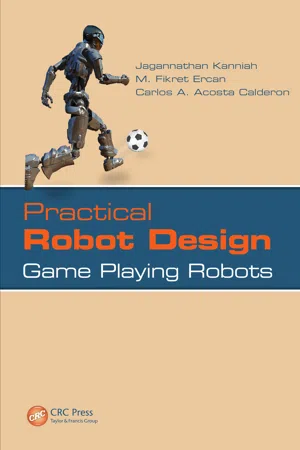
Practical Robot Design
Game Playing Robots
- Jagannathan Kanniah, M. Fikret Ercan, Carlos A. Acosta Calderon(Authors)
- 2013(Publication Date)
- CRC Press(Publisher)
Clayton (1969), Say (1984), Cotton (1970), McKenzie-Smith and Hughes (1995), Fitzgerald et al. (1990), and Langsdorf (2001) are valuable resources for further read-ing on electrical machines. 5.1 ACTUATORS FOR ROBOTS Robots need some source of torque and power to accomplish the desired motion; in other words, every robot needs some form of actuation. The devices that provide that actuation are in general called “actuators.” When a robot moves on a terrain on wheels, the motion needs to be generated by a drive system with one or more prime movers. When a robot moves its arm, in most cases, there is a power source inside every joint, which is actually moving the arm. In comparison, when a human being is moving each joint in an arm, the motion is generated by some pushing and pulling caused by muscles. This type of mechanism governs the motion of many living organ-isms. Accomplishing the same mechanism is very complex for man-made systems. In 5 104 Practical Robot Design most cases, a joint itself is self-powered and provides the motion desired. There are various types of actuators that can be used in robotics. They can be largely classified as electrical, pneumatic, and hydraulic. In mobile robots, pneumatic actuators are used occasionally if there is a need for a very high torque. A main disadvantage is that the system requires an external air supply to operate. Hydraulic actuators are common in earthmoving machines. We may come across hydraulic actuators on mobile robots as well, although these are exceptions. In this book, we will focus only on electrical devices as most game robots work with electrical actuators. 5.2 ELECTRICAL ACTUATORS Electrical actuators are electrical motors, which are mainly classified as AC (alter-nating current) and DC (direct current) motors. AC drives are seldom used in mobile robots or game-playing robots. Usually, powerful industrial robots operating in man-ufacturing lines use AC drives. - eBook - PDF
Mechatronics
A Foundation Course
- Clarence W. de Silva(Author)
- 2010(Publication Date)
- CRC Press(Publisher)
465 7 Actuators Study Objectives The purpose of actuators in a mechatronic system • Types of actuators • Stepper motors and dc motors (including brushless dc motors) • AC motors (induction motors and synchronous motors) • Linear actuators • Hydraulic and pneumatic actuators • Modeling and analysis of actuators • Practical performance and parameters of actuators • Sizing and selection of actuators for practical applications • Instrumentation, drive hardware, and control of actuators • 7.1 Introduction This chapter introduces the subject of actuators, as related to mechatronics. The actua-tor is the device that mechanically drives a mechatronic system. Joint motors in a robotic manipulator are good examples of such actuators. Actuators may be used as well to oper-ate controller components (final control elements), such as servovalves, as well. Actuators in this category are termed control actuators . Actuators that automatically use response error signals from a process in feedback to correct the operation of the process (i.e., to drive the process to achieve a desired response) are termed servoactuators . In particular, the motors that use measurements of position, speed, and perhaps load torque and armature current or field current in feedback to drive a load to realize a specified motion are termed servomotors . One broad classification separates actuators into two types: incremental-drive actuators and continuous-drive actuators. Stepper motors, which are driven in fixed angular steps, represent the class of incremental-drive actuators. They can be considered to be digital actuators, which are pulse-driven devices. Each pulse received at the driver of a digital actuator causes the actuator to move by a predetermined, fixed increment of displacement. Continuous-drive devices are very popular in mechatronic applications. Examples are direct current (dc) torque motors, induction motors, hydraulic and pneumatic motors, and piston-cylinder drives (rams). - eBook - PDF
Emerging Actuator Technologies
A Micromechatronic Approach
- José L. Pons(Author)
- 2005(Publication Date)
- Wiley(Publisher)
ACTUATORS IN MOTION CONTROL SYSTEMS: MECHATRONICS 23 Rotor Elastic substrate Wave propagation (a) (b) Piezoelectric ceramic Figure 1.17 Biological model for travelling wave ultrasonic linear and rotational motors. motions) an effective elliptic displacement at the interface between rotor and stator (see Figure 1.17b). This provides traction through a frictional transmission. 1.5 Concomitant actuation and sensing: smart structures In previous sections, we discussed how transducing devices can be configured either as sensors or as actuators. Here, we stress the fact that transducers can implement both crucial roles – sensing and actuation – in a motion control system. The former provides a tool for monitoring the status of a system and the latter enables us to impose a condition on a system. In some special cases, transducers can be used both as sensors and as actu- ators. Take for instance, DC electromagnetic motors. Rotational electromagnetic motors can function both as actuators (i.e. rotational mechanical energy is pro- duced by the application of a driving voltage), and as generators (i.e. the rotation of the output shaft produces a voltage, proportional to the rotation rate, at the electrical terminals). Let us consider the case of a permanent magnet DC electromagnetic motor. DC electromagnetic actuators make use of Lorentz’s electromagnetic interaction between a permanent magnetic flux, B , and an electrical current, i , flowing in a coil (see Figure 1.3). In an appropriate configuration, if the coil is allowed to rotate, the magnetic interaction produces a torque, T , on the coil, causing rotation. The torque developed by the electromagnetic interaction can be expressed as: T = k T i (1.13) where k T is the so-called torque constant of the DC motor. Similarly, since the DC motor coil is rotating in a magnetic field, induction will take place and a (back) electromagnetic voltage (EMF) will be induced. The - eBook - PDF
MEMS
A Practical Guide to Design, Analysis and Applications
- Jan Korvink, Oliver Paul(Authors)
- 2005(Publication Date)
- William Andrew(Publisher)
To limit the scope of this chapter, we will discuss microactuators that are physically smaller than 1 mm 3 and made of critical components less than 1 mm in size, or that are produced with micromachining process technologies. 752 MEMS: D ESIGN , A NALYSIS , AND A PPLICATIONS 14.2 Actuators: Transducers with Mechanical Output An actuactor is a device that converts energy from one form, such as electrical, mechanical, thermal, magnetic, chemical, and radiation energy, into the mechanical form. (For example, resistive heating elements con-vert electrical energy into bending of a bimorph microstructure.) In some cases, a microactuator may convert energy into intermediate forms before resulting in the final mechanical output (such as inductively coupled heat-ing elements, which convert electrical energy first into magnetic energy before finally resulting in thermal energy serving to deflect a microele-ment). Such devices are said to be based on tandem transduction. In some actuators, the mechanical output signal is in turn used to direct or modulate a nonmechanical signal. This situation is encountered in numerous optical applications, many of which are described in detail in Chapter 7. 14.2.1 Transduction Mechanisms Prominent actuation mechanisms used in MEMS are listed in Table 14.1. Specific examples of MEMS actuators that make use of these trans-duction mechanisms are described, analyzed, compared, and contrasted throughout the rest of this chapter. Each mechanism has its own advantages, disadvantages, and appro-priate set of applications. Electromechanical transduction mainly relies on two mechanisms. The first makes use of electrostatic forces to attract or Table 14.1 Common Microactuation Mechanisms Input Output: Mechanical Electrical Electrostatics Piezoelectricity Magnetic Magnetostatics Magnetostriction Mechanical Pneumatics Hydraulics Thermal Expansion Shape memory effect Phase change Chemical Combustion - eBook - PDF
Meso- to Micro- Actuators
A Theoretical and Practical Approach
- Alberto Borboni(Author)
- 2008(Publication Date)
- CRC Press(Publisher)
156 Meso- to Micro-Actuators: A Theoretical and Practical Approach tify the net electric power P E usable for the conversion into mechanical power P M . Therefore, neglecting the friction phenomena, the expression (2.25) can be a reference to identify an ideal system of electromechanical conversion. P V i Blu i P F u Bli u E M = ⋅ = ⋅ = ⋅ = ⋅ (2.25) The expression (2.25), which represents the equivalence between electric power P E and mechanical power P M exchanged into the ideal actuator, opens the door to the concept of ideal electromechanical transformer (Lynch and Truxal 1962), allowing an interesting circuital representation (Figure 2.24), where the mechanical component is constituted by an ideal force generator that depends on the electric current i flowing the bar, although the electric component is constituted by an ideal tension depending on the mechanical speed u of the bar. To improve the accuracy of the lumped parameters model, an electric resistance R and the coefficient r of mechanical friction can be introduced to represent the dissipative factors, whereas the inertial properties can be identified with a mass M and the respective inductive properties can be asso-ciated with an inductance L , resulting in an increment of one order of differ-entiability for the mathematical model expressed by (2.26) and represented by the circuital scheme in Figure 2.25. V Ri L di dt Blu F ru M du dt Bli − − = − − = − (2.26) Blu + – V + – u + – Bli F i FIGURE 2.24 Circuital model of an ideal electromechanical transformer. Modeling Actuators 157 2.3.2 Electromagnetic Transducer A magnetic circuit is constituted by an electromagnet provided with a com-ponent rigidly constrained to the frame and electrically fed, and by a mobile component hinged to the previous one; this configuration identifies, rigor-ously, a rotary actuator, but, for the slightness of the stroke, it can be approxi-mated to a prismatic actuator. - eBook - PDF
Micromechatronics
Modeling, Analysis, and Design with MATLAB, Second Edition
- Victor Giurgiutiu, Sergey Edward Lyshevski(Authors)
- 2016(Publication Date)
- CRC Press(Publisher)
Each electrostatic microactuator is con-trolled, and the settling time is 0.0001 s. To actuate any mechanism, the developed electro-static force or torque must be greater than the load force or torque. The actuator integration, packaging, housing, and other aspects are examined. Hence, while in conventional and miniscale mechatronic systems, the electromagnetic actuators ensure the superiority, in MEMS, the electrostatic, thermal, and piezoelectric actuators may be a preferable solution. Using the CMOS technology integrated with the bulk and surface micromachining processing, the images of fabricated structures, electromagnetic actuators (with deposited coils on 30 m m silicon diaphragm), and electrostatic actuator are reported in Figure 3.1. For the micromachined electromagnetic actuators, as documented on Figure 3.1b, the de fl ection of the diaphragm is measured by using the variations of resistances of four polysilicon resistors that form the Wheatstone bridge. By using W e ¼ 1 2 Ð v r v Vdv , the potential energy stored in the electric fi eld between two surfaces (capacitor) is W e ¼ 1 2 QV ¼ 1 2 CV 2 . The force-and torque-energy relations were reported in Chapter 2. The energy stored in the capacitor is 1 2 CV 2 , while the energy stored in the inductor is 1 2 Li 2 . The energy in the capacitor is stored in the electric fi eld between plates, while the energy in the inductor is stored in the magnetic fi eld within the coils. Considering device physics of electromechanical motion devices [1 – 6], the major torque production and energy conversion mechanisms that lead to the corresponding operation should be emphasized. In particular, the devise physics of electromagnetic devices is based on (c) (a) (b) FIGURE 3.1 (a) Etched silicon structure and cross-section of a 35 m m silicon diaphragm; (b) micromachined 1 1 mm electromagnetic and thermal actuators with displacement sensors; (c) micromachined electrostatic actuator with the suspended (released) plate. - Figure 5.1 illustrates how mechanical micromachines fit into the scheme of machines and micro-machines. From a functional standpoint, a mechanical machine is a system composed of an actuator, a transmis-sion, and a user. The actuator generates the mechanical work; the transmission transforms this work and connects the actuator with the user; and the user acts directly on the environment (Figure 5.2). A microactuator can have macro dimensions to generate a microenvironmental perturbation; how-ever, for our purposes, we will consider actuators with at least one dimension in the order of microns (less than 1 mm), so we are referring to micromechanical actuators in the strictest sense (Figure 5.3). In this chapter, the term microactuator will be used to describe a micromechanical actuator of less than 1 mm or almost in the strictest sense (a very small micromechanical actuator larger than 1 mm). 5 -1 Alberto Borboni Università degli studi di Brescia 5.1.1 Functional Characteristics and Choosing Criteria The functional characteristics of an actuator are those of its mechanical output. These can be described by the relationship between generated torque and angular speed (if the actuator produces a rotary motion) or by the relationship between generated force and linear speed (if the actuator produces a lin-ear motion). For this discussion, we will assume a rotary motion. If the motor is operating under steady-state conditions (input power, load to overcome, and the environment are constant) then the relationship between generated torque and angular speed can be graphed by a line on the torque-speed plane. This relationship is called the actuator characteristic (Figure 5.4).
Index pages curate the most relevant extracts from our library of academic textbooks. They’ve been created using an in-house natural language model (NLM), each adding context and meaning to key research topics.
